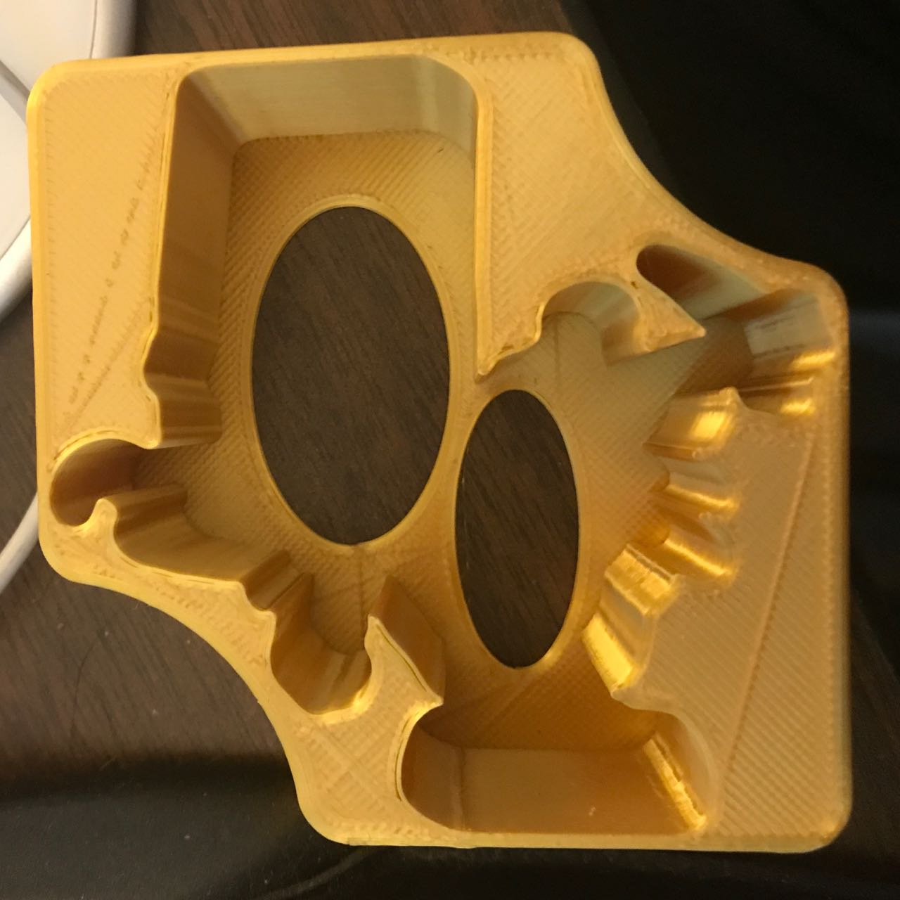
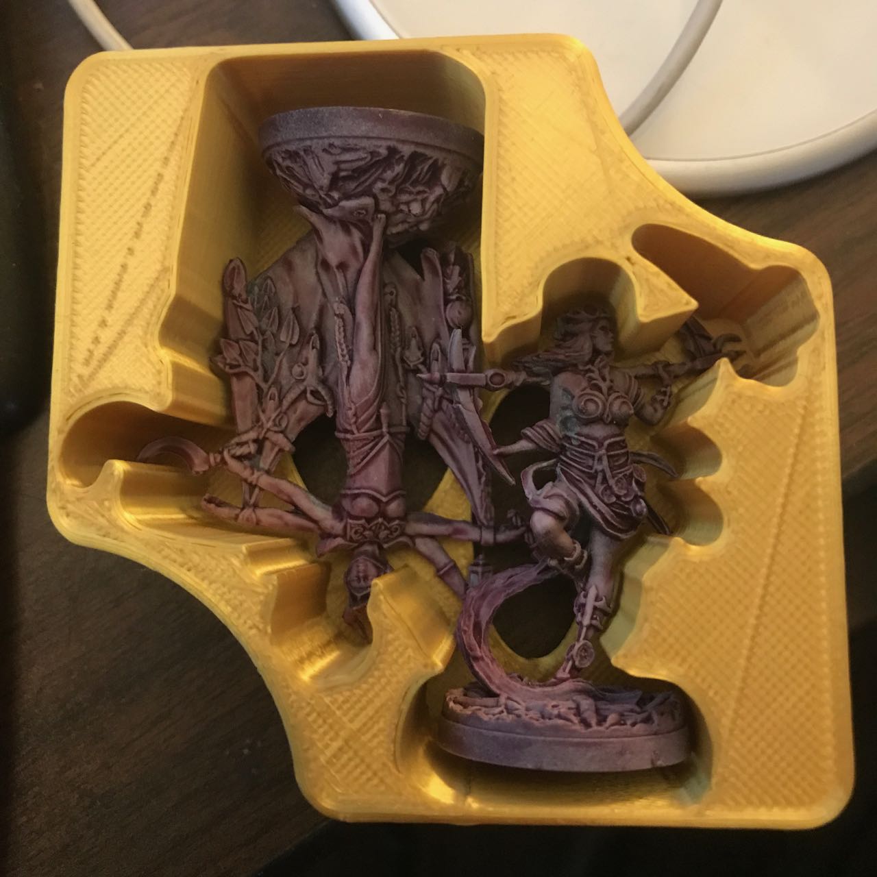
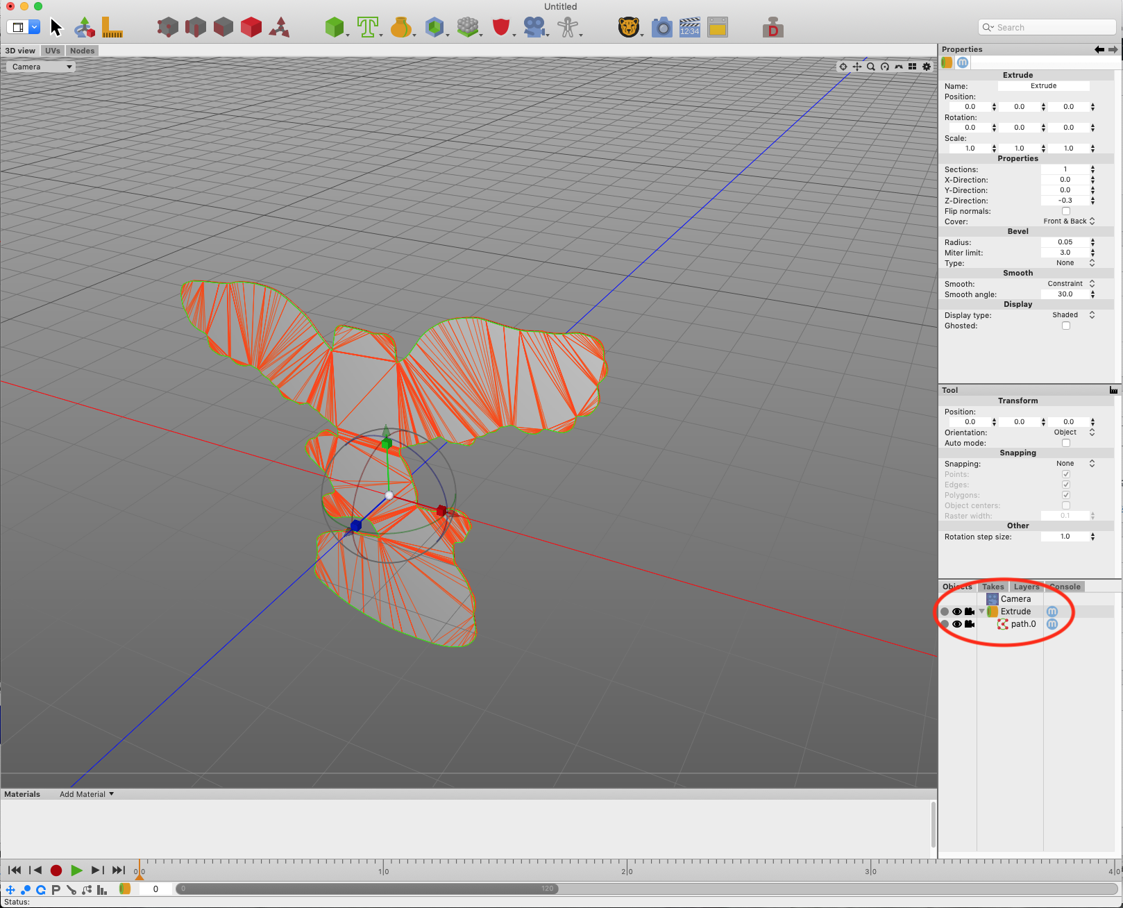
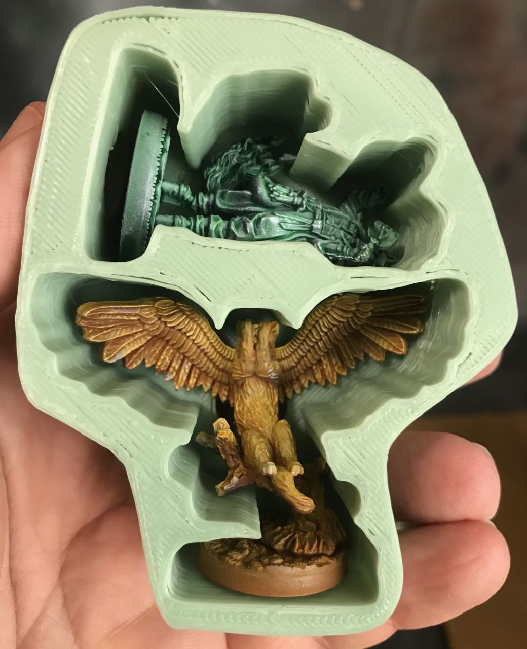
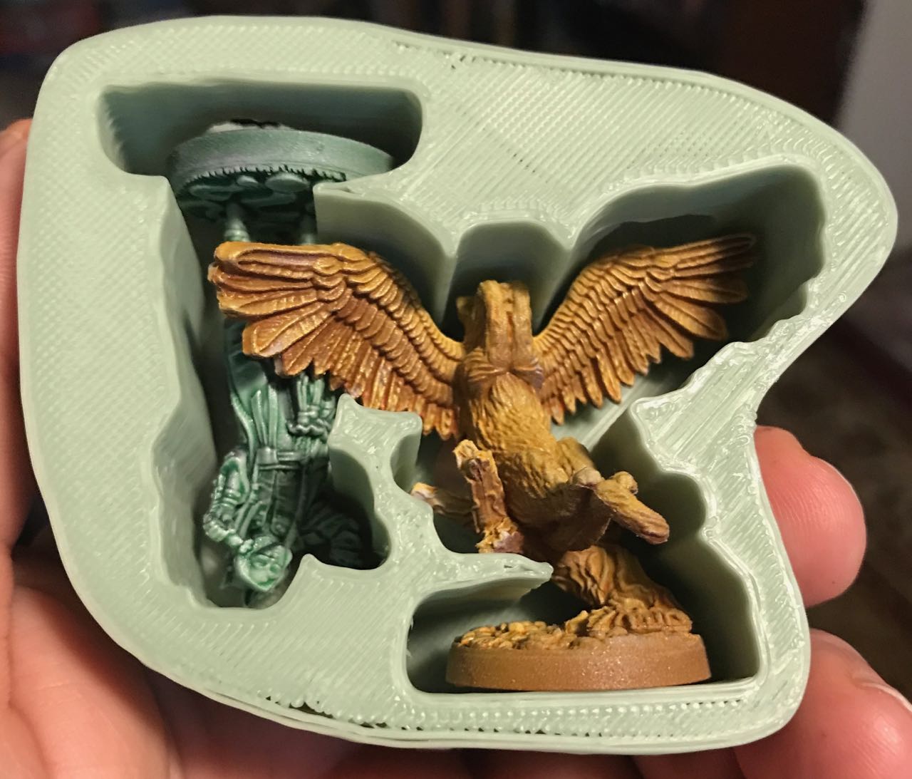
For the first wave of the game Etherfields, I received a fifth-player expansion. It included two additional miniature figures to play that fifth character, the Reaper. To store and transport those figures, I downloaded and 3D printed a holder that someone else designed:
I recently received the second wave of Etherfields content. It included lots more minis. I’ll eventually write one of my usual picture-filled posts of how I painted them.
This post focuses on a different issue: I want to safely transport some of those minis when I go to play Etherfields at my friends’ home. There are many miniature figures storage solutions out there, but they’re a bit pricey, too bulky, and hard to customize for the elaborate sculpts of Awaken Realms‘ miniatures.
I could always hope that someone will design a holder for the miniatures I want to carry and upload it to a 3D-design site like Thingiverse, as I did for the above miniatures. Instead, I decided to figure out how to design and print my own holders. In the spirit of my long posts on creating gadgets, I’m going to share how I did it.
Acknowledgement: I could not have done this without assistance from Vann (link possibly NSFW; fortunately I work from home).
Caveats
The first obvious caution is that this is definitely a “Golly, gee whiz!” post. If you’re an experienced designer or modeler, the only reason to read this post is to look at the pretty pictures and/or to laugh.
The other warning is that the tools I describe below are all Macintosh-specific. They’re not even the most commonly-used design tools on the Mac for these functions. I tried to make use of the more popular and free tools available, but I was stumped by the learning curve. I’ll mention other tools below, but all the screen shots come from the programs I used.
Therefore, I strongly suggest that you focus on the techniques, not the tools. For example, when I talk about “extruding a spline curve,” for you that probably means to look up how to extrude a planar object in your favorite 3D program, not to use Cheetah3D and select Object->Creator->Extrude from the menus.
In other words, you don’t have to buy a Macintosh just to run Pixelmater Pro. There’s something else out there that can do the same thing, probably for free.
Step 1: Take a picture
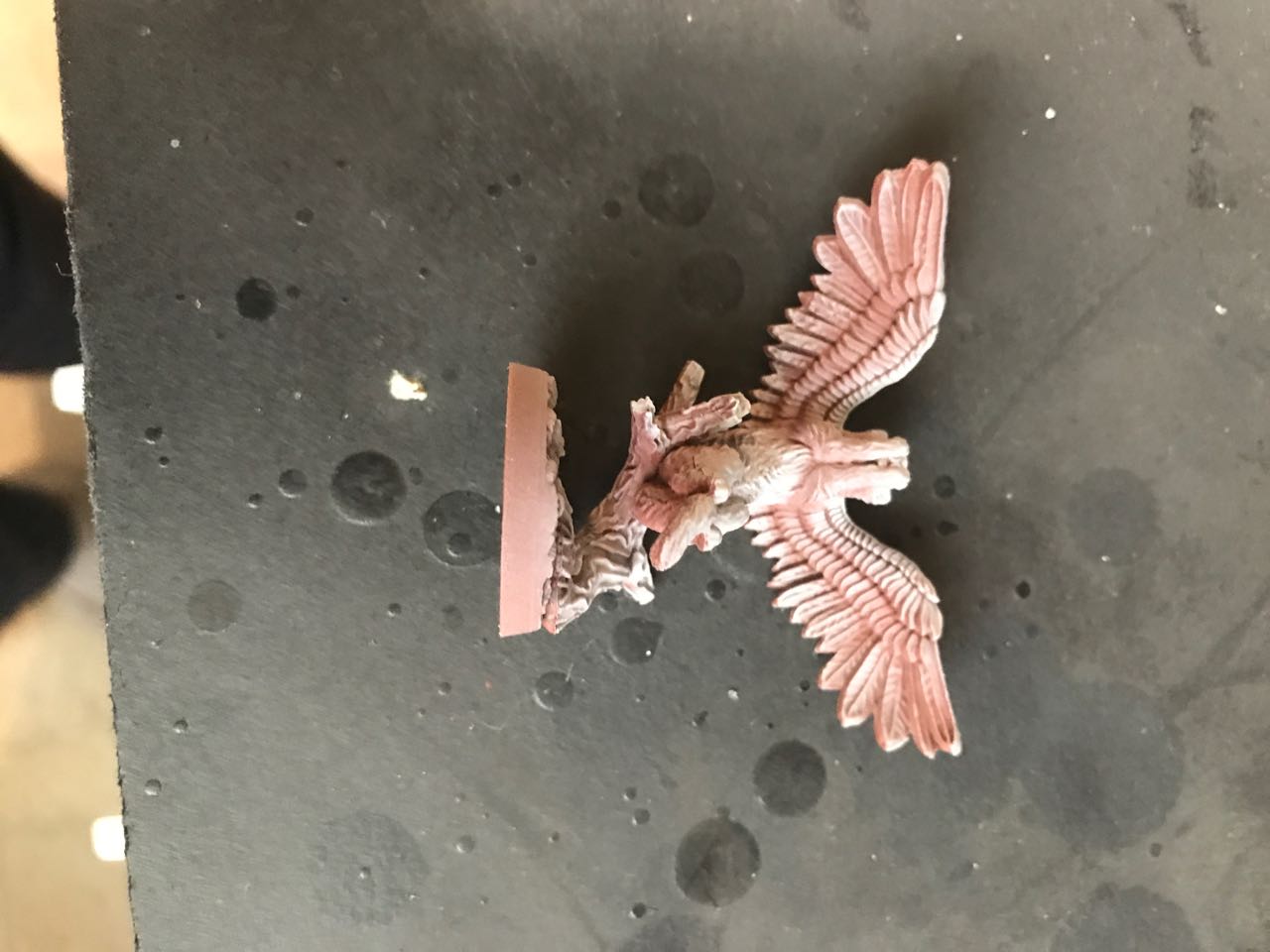
The first step is to take a photo of the mini you want to store. It doesn’t have to be a great picture. You’re just trying to capture the shape.
A couple of minor hints:
- Orient the mini in the way you want it to slide in the holder. This probably means take a picture “head-on.” Take care not to take the picture from “above” or “below” the mini; you probably want the base to appear flat, for example.
- Make sure there’s at least some modest contrast between the mini and its background. This will make it easier to select the mini’s shape in your image program (see below),
Here’s an example:
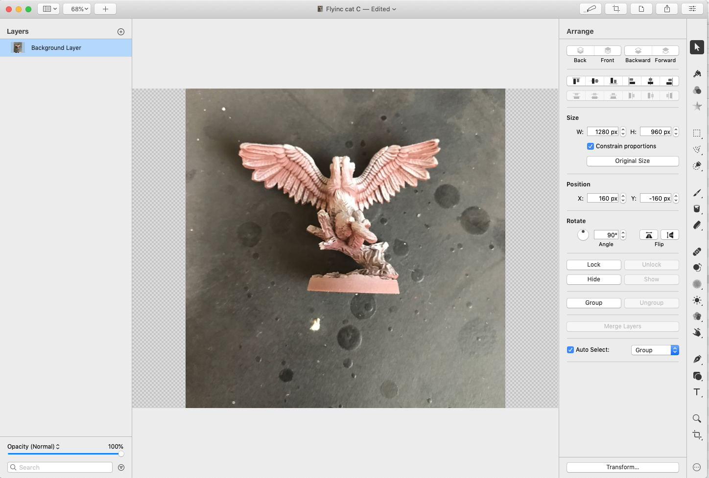
Step 2: Select the mini’s image
For the next couple of steps, you’ll need an image-processing program. As I mentioned above, I used Pixelmater Pro. For this kind of work, any mid-range or higher image program will do. Obviously, the “500-lb gorilla” in this field is Adobe Photoshop, which is fiendishly expensive and (at least for me) intimidating to use. The free open-source program GIMP will work too, and runs on Mac/Windows/Linux.
I loaded the picture into Pixelmater Pro:
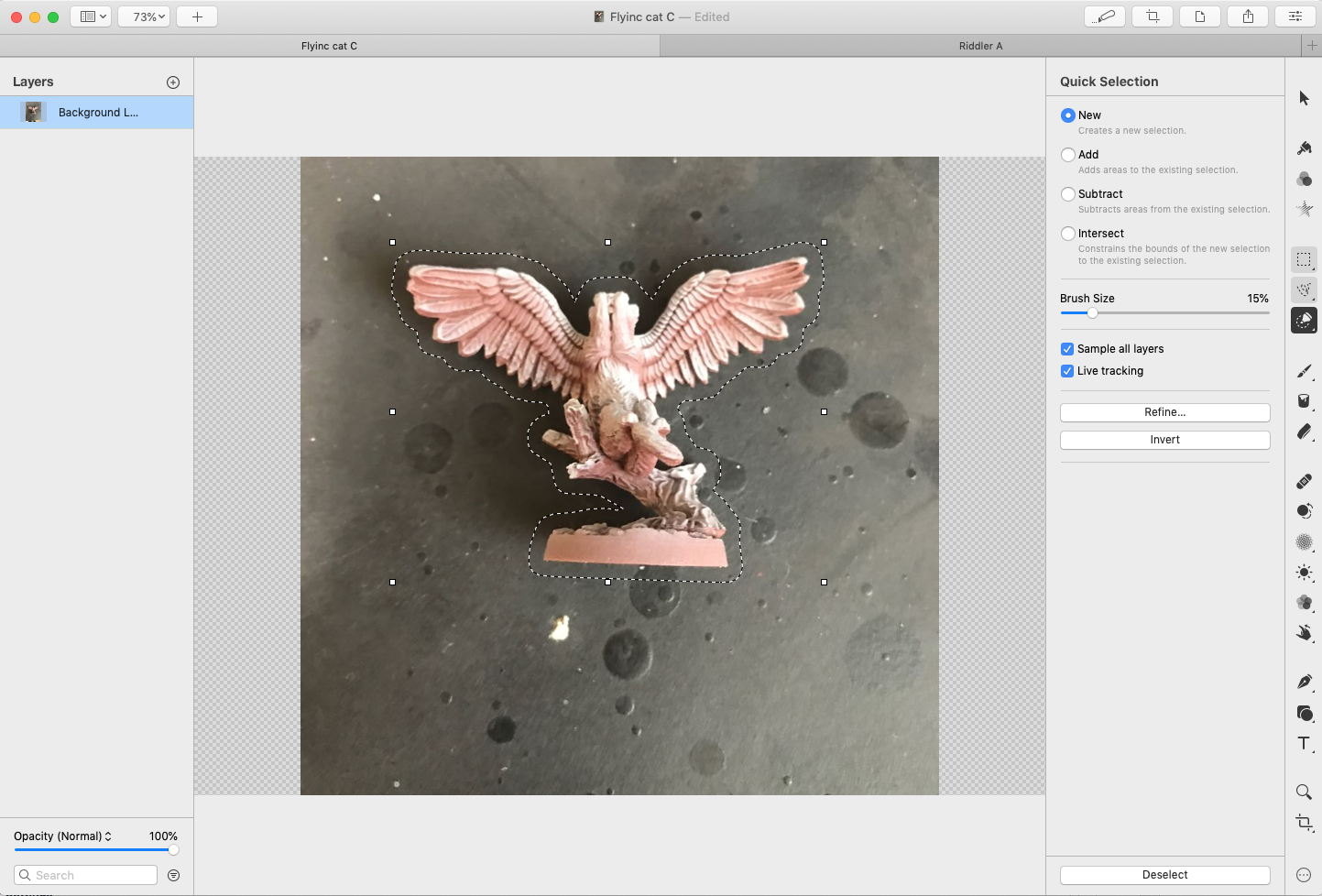
I used the Quick Selection tool:

I held the left mouse button down until I highlighted everything except the image of the mini:
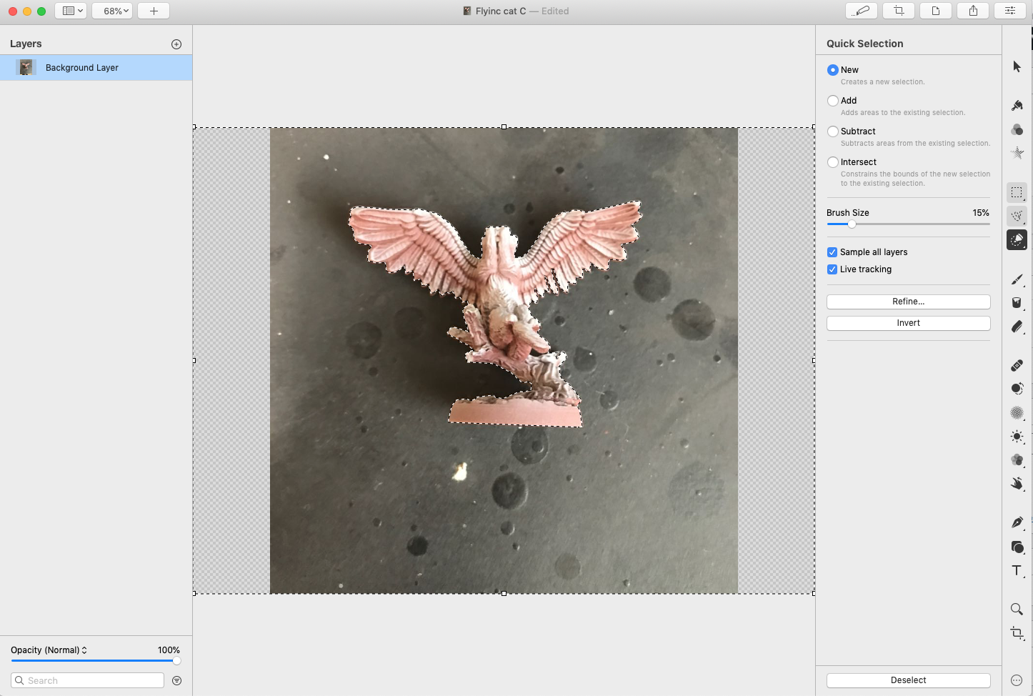
The reason to highlight everything but the mini is to handle the case when the mini image has “holes” in it.
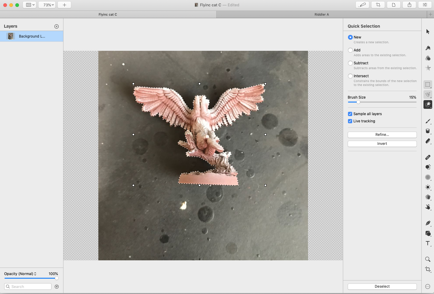
I then clicked on the Invert button in Quick Select panel to select only the image of the mini.
I know it’s a lot of pictures. But after you’ve done it a couple of times, it’s just a few clicks and drags.
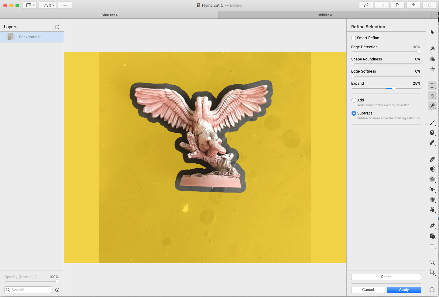
Step 3: Grow the selection
The point of making this selection is to define the “hole” we’re going to place into the miniature holder. However, if we made the hole the exact shape of the mini, even if we simply scaled it bigger, the mini probably wouldn’t fit.
What we want to do is expand that selection evenly around that outline. This will define a hole that’s more likely to fit the mini.
Fortunately, this is a common image task. Any of the image programs I’ve mentioned can do it. In Pixelmator Pro, this function is found by clicking the Refine… button, just above the Invert button in the pictures above.
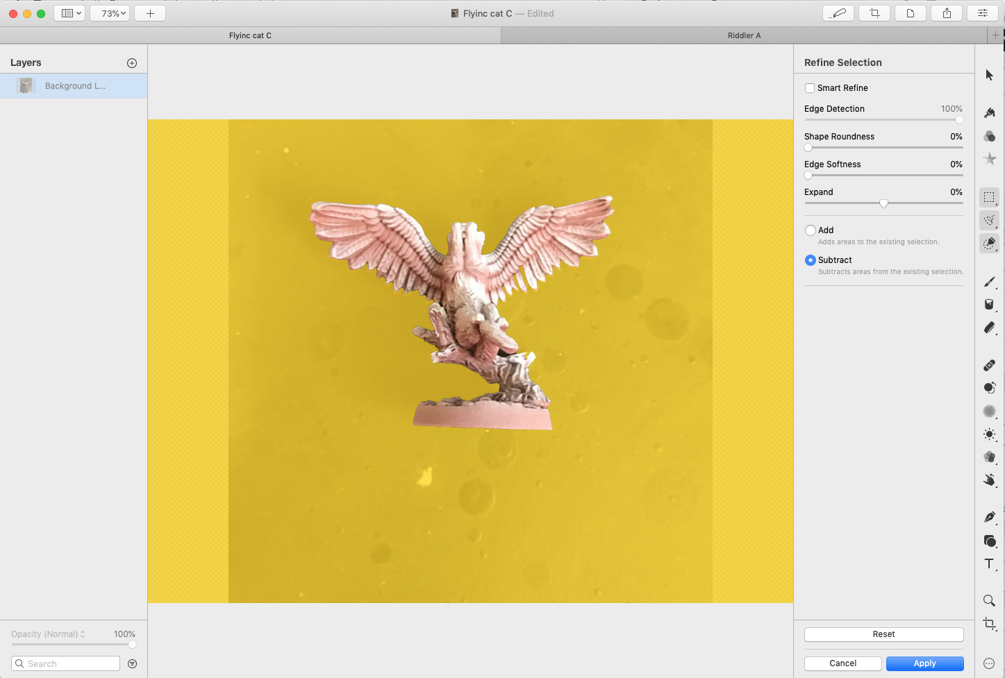
Drag on the Expand slider to grow the outline of the selection. (In GIMP, this same functionality is called Grow.)
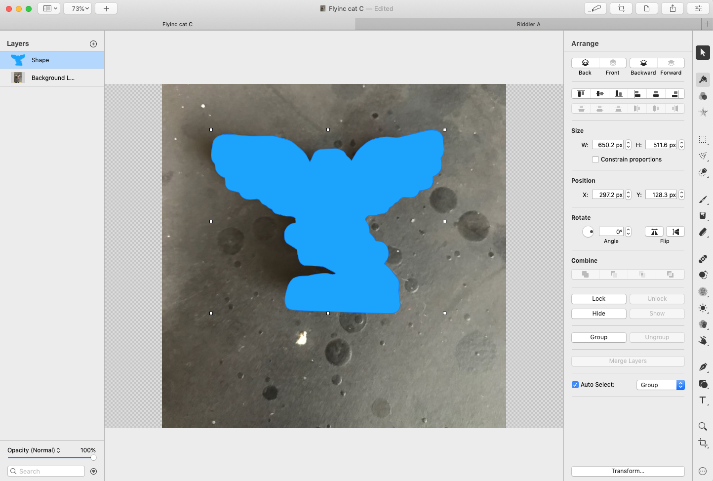
Step 4: Turn the selection into a vector graphic
Next, we want to turn that selection outline into a format that can be imported by a 3D-design program. Pixelmater Pro can export in SVG format, but first we have to turn that “outline” into a shape. In Pixelmater Pro, that command is the menu Format->Convert into Shape:
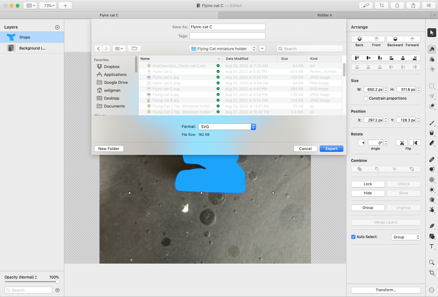
To save the shape in SVG format, in Pixelmater Pro select File->Export… and make sure the export format is SVG:
Interlude: 3D design programs
In anticipation of this blog post, I tried to use the free web site OnShape. I managed to get the task done, but just barely:
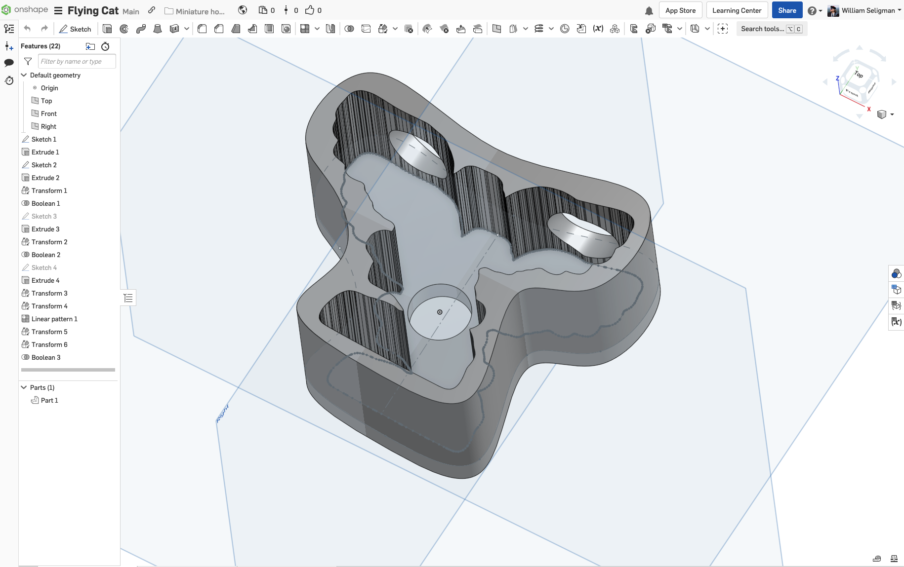
The problem, for me, is that OnShape is designed for engineers, and has a user interface that I believe follows the standard for CAD programs. This means that the program does not respond the way I was used to with Mac programs. For example, if I clicked on some graphical object in a Mac program, I expect that object to be highlighted, and perhaps some information about that object to be displayed. In OnShape, if you click on an object, what happens can be generously described as “unpredictable.” Unbelievably for an engineering program, the object’s properties (such as size or location) are not displayed when you select it.
If you’re familiar with a CAD program, OnShape is definitely the tool for you (though you’d probably use that CAD program in the first place, as opposed to any of the other tools I describe below). Otherwise, I suggest looking elsewhere.
As I mentioned above, the 3D-design program I use is Cheetah3D. It’s oriented around the needs of graphic designers and low-end animators. I used it to design all the items in my jewelry shop. For me, it was the appropriate tool because I’m familiar with it.
Another program to consider is the free Blender. I’ve tried it a couple of times. I found it to be tricky to use, but that’s probably because I’m too used to Cheetah3D. Blender is to 3D design what GIMP is to image manipulation: free, open-source, runs on Mac/Windows/Linux, reasonably well-documented and supported, but there is some learning curve if you’re used to something else.
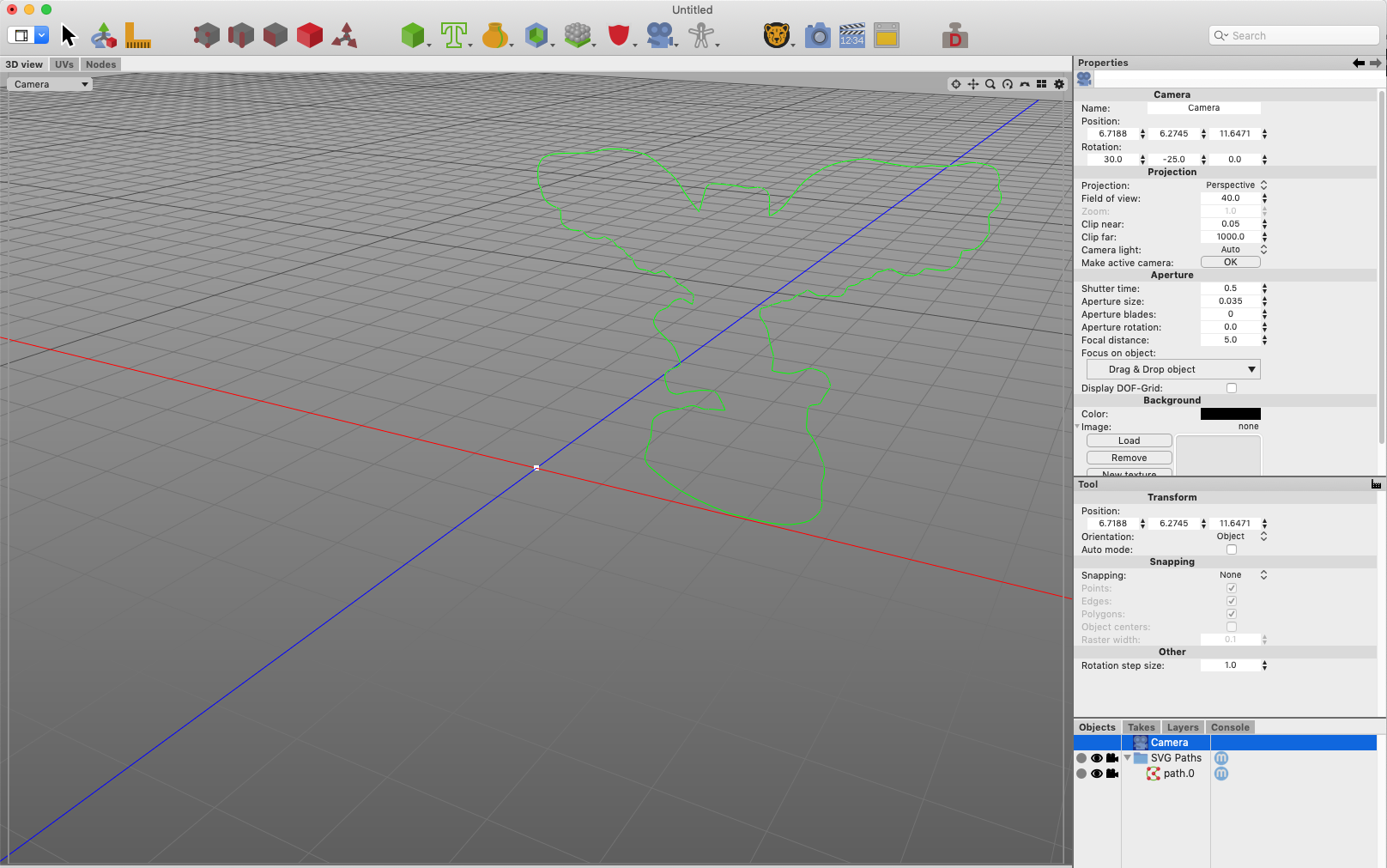
Step 5: Import the shape into your 3D program
In Cheetah3D, this is just a matter of selecting the menu File->Import…:
Some 3D programs (OnShape in particular) won’t import SVG files, but will import DXF files. There are lots of free web-based tools for converting SVG to DXF; here’s the one I used for my OnShape test. There are also plenty of free programs that can do this; if I’d had to do this more than once, I probably would have installed the free open-source program Inkscape, which is available for all major operating systems.
Step 6: Scale the shape
This is the tricky part, both to understand and to do.
So far, the shape we’ve manipulated is “dimensionless.” How big is it? You might be tempted to give an answer in pixels or something like that. The reality is that we haven’t established a size for this shape in any units that a 3D slicing program (our eventual destination) can use.
The next step is to measure the size of the mini. I prefer to use digital calipers:
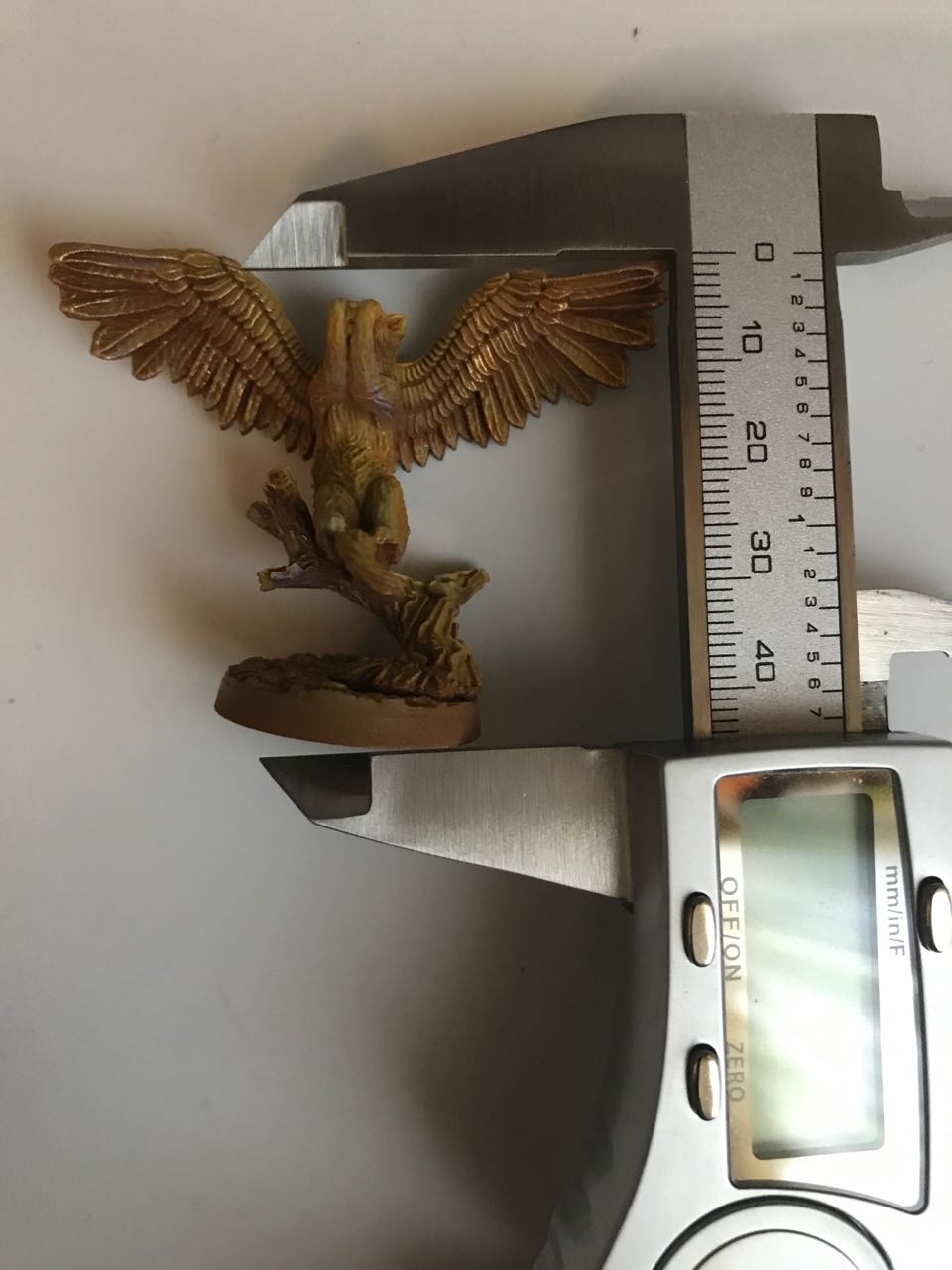
Now that we have the size of the mini, we have to decide the size of the shape. After a bit of experience (see the above picture), I found that adding 3mm to the height of the mini would create a shape large enough so that I could be fairly confident that mini would fit into the resultant hole (which we’ll make below).
In OnShape, scaling something to a particular size is a mix of easier and harder than it is in Cheetah3D. On the one hand, in OnShape you can create a “construction line,” add a dimension display to that construction line, then type in a value to that dimension to scale that line and whatever it’s attached to. On the other hand, creating the construction and dimension lines is much harder than it should be; it took me a lot of trial and error, and I couldn’t remember exactly what set of mouse clicks and drags were needed to do it again.
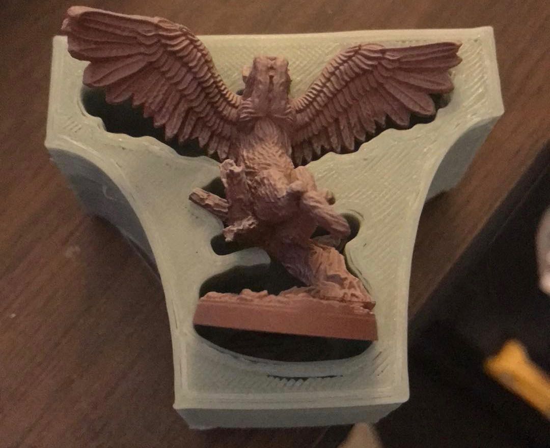
In Cheetah3D, there’s no automated scaling of that sort. What I did was create a “ruler”; in this case, a box that was 48mm high (the measured height of my mini was 45mm, then I added 3mm):
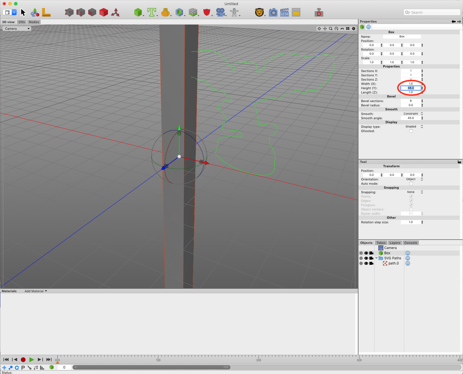
Using the “ruler box” as a guide, I scaled up the shape:
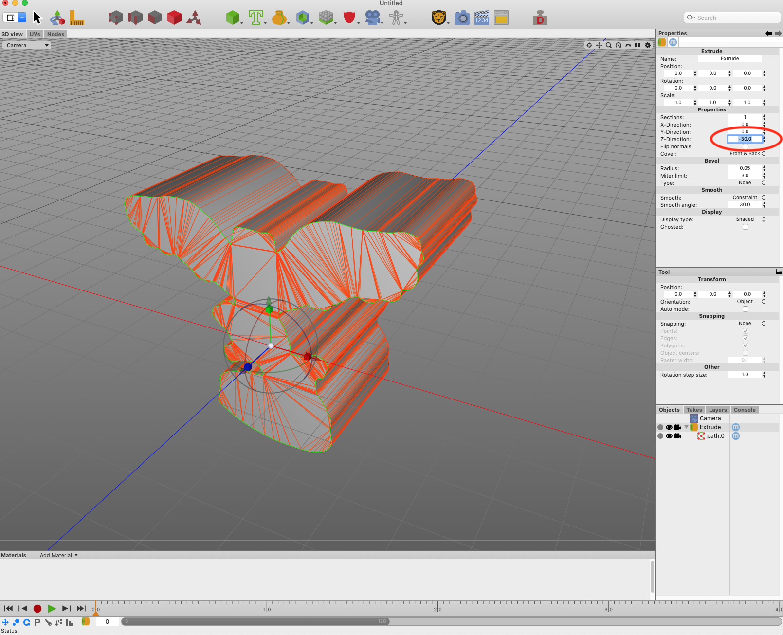
Step 7: Extrude the shape
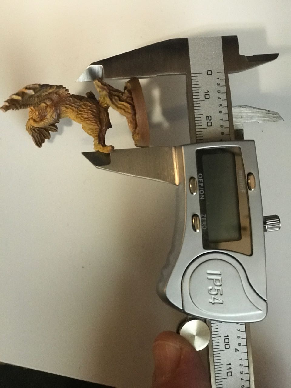
We have the shape of the hole. Now we have to set the depth of the hole.
In our case, the second picture with the calipers above shows that the depth of the hole has to be at least 25mm to accommodate the mini. Let’s make it 30mm just to be safe.
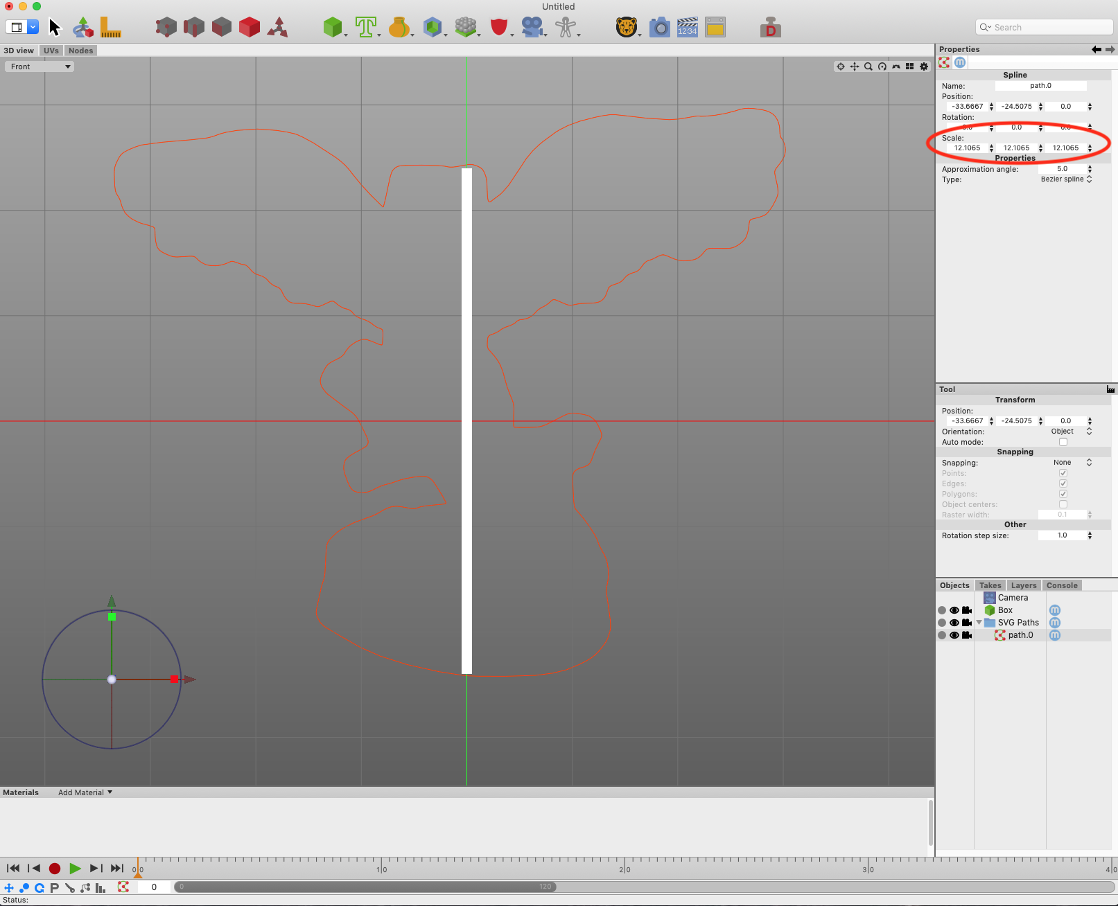
I deleted my “ruler box.” Then I used the extrusion tool in Cheetah3D to create a 30mm extrusion along the z-axis.
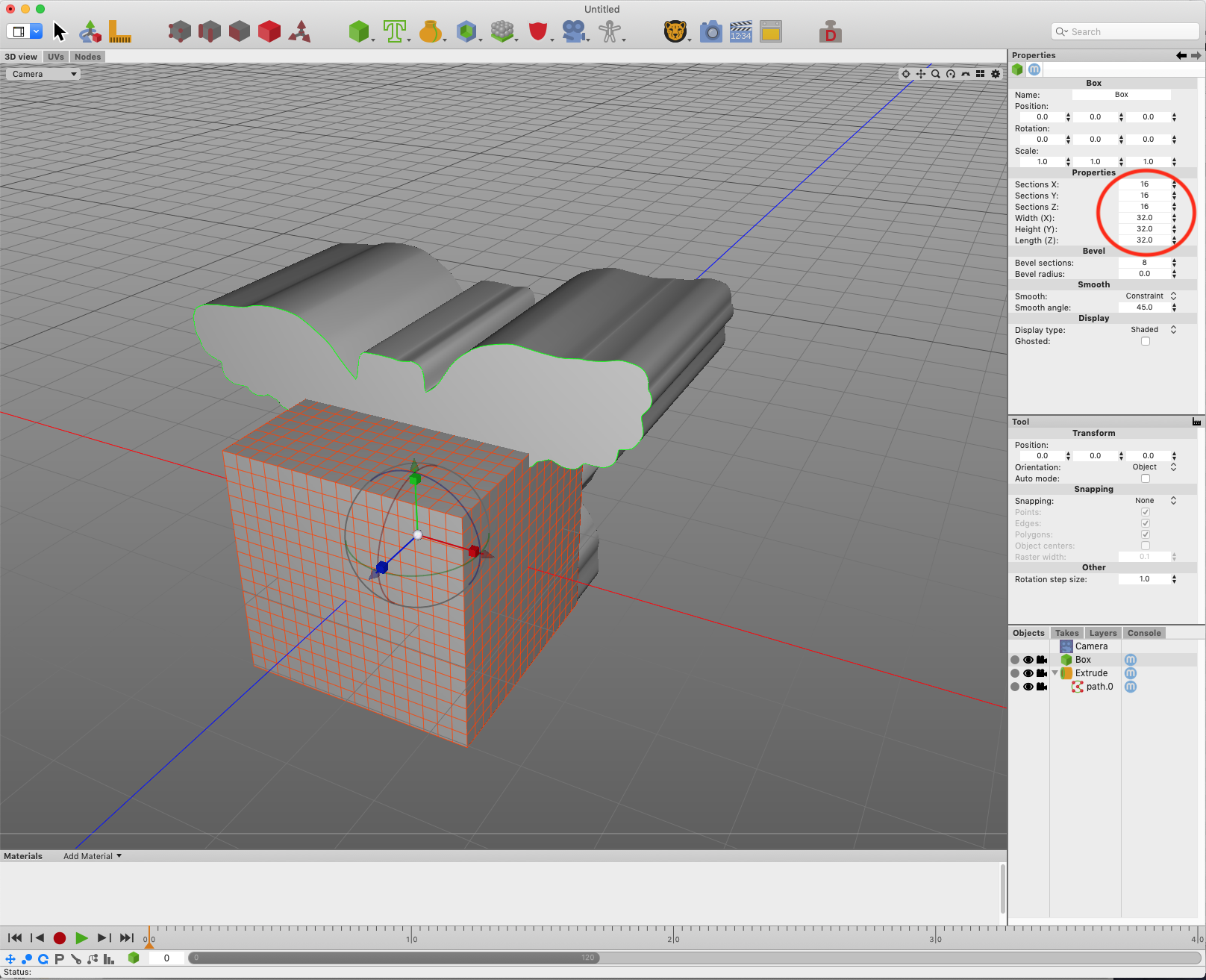
Step 8: Turn it into a hole
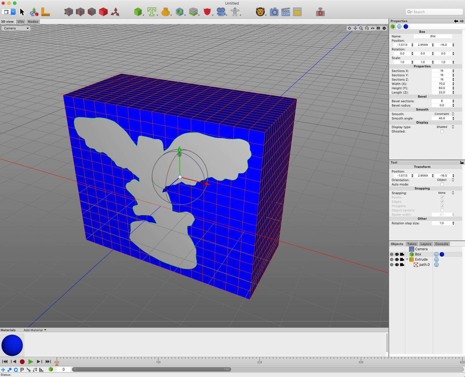
That extruded shape is going to become the hole in our miniature holder. Let’s now think about a box into which we’ll put our hole.
We already know that the depth of the hole will be 30mm. How thick should be the “floor” of the holder be? 2mm is probably enough. That means the box’s total depth will be 30mm + 2mm = 32mm. I’ll start by making the height and width of the box 32mm as well, because I have to start with something.
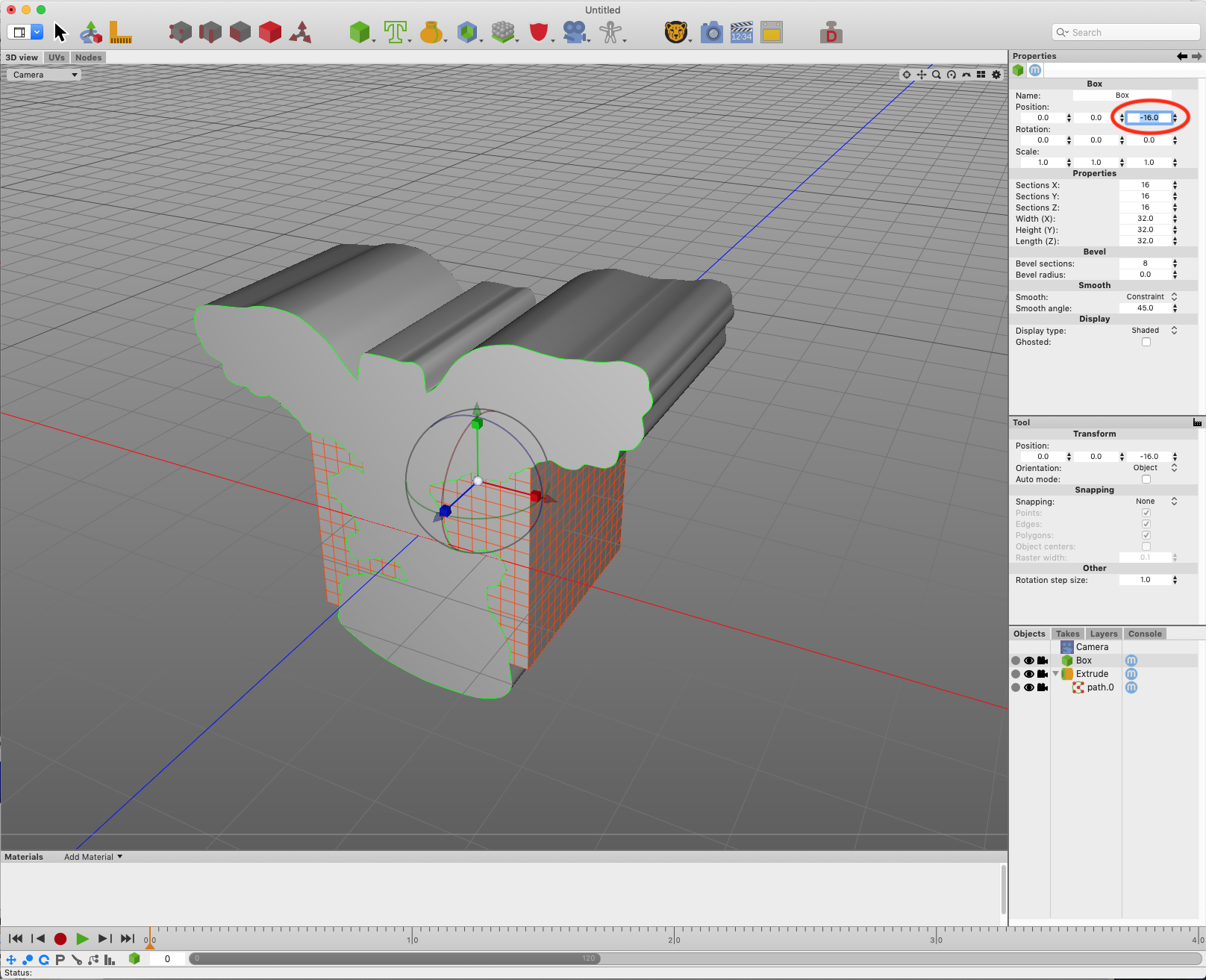
Position the box so its front face is at the same position as the front face of our shape’s extrusion.
Adjust the size of the box to fit the shape.
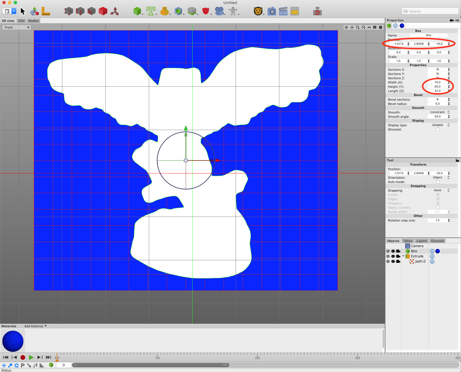
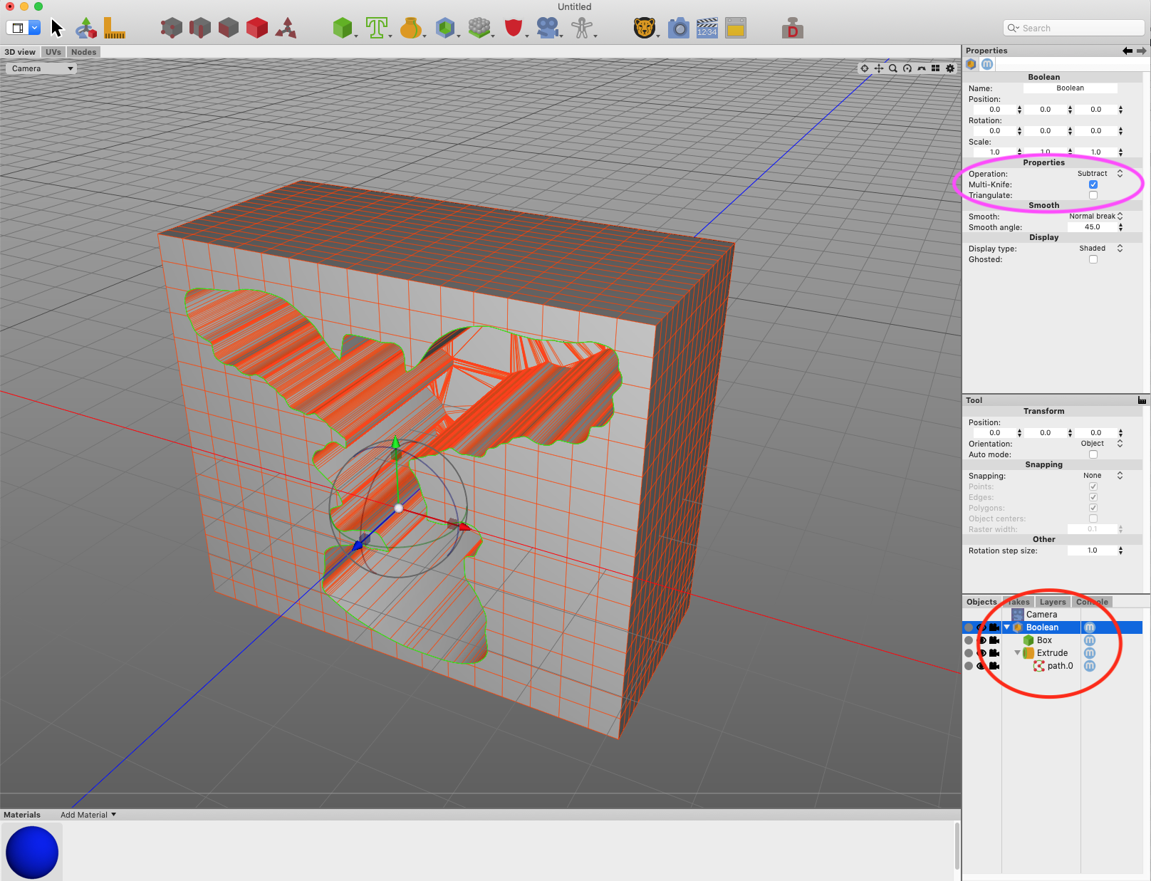
Now we come to the fun part! We’ll use “boolean subtraction” to carve out the material of extruded shape from the box.
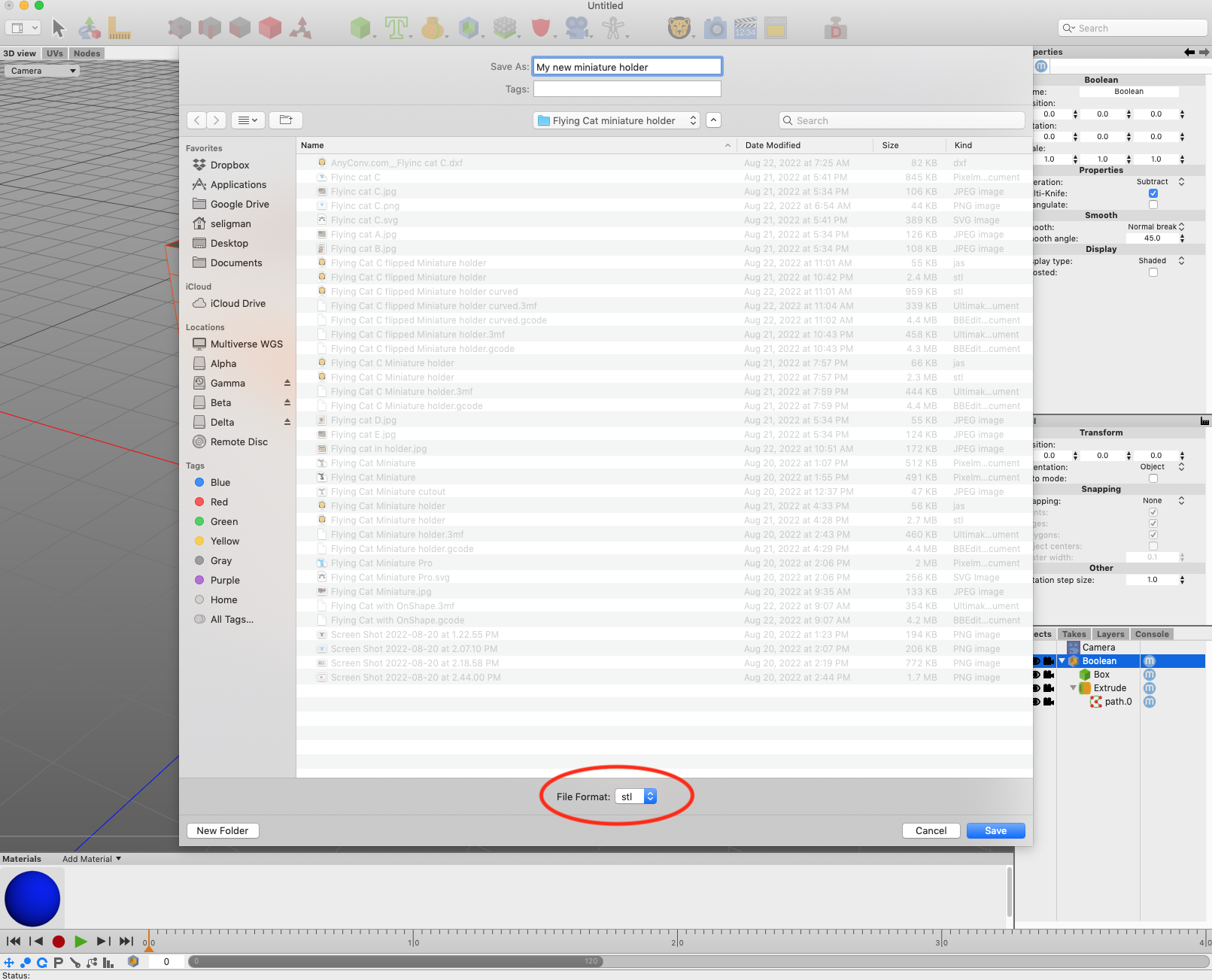
Step 9: Save the whole thing as an STL file
This is trivial: Export the resultant shape in a format that a “slicer” can read.
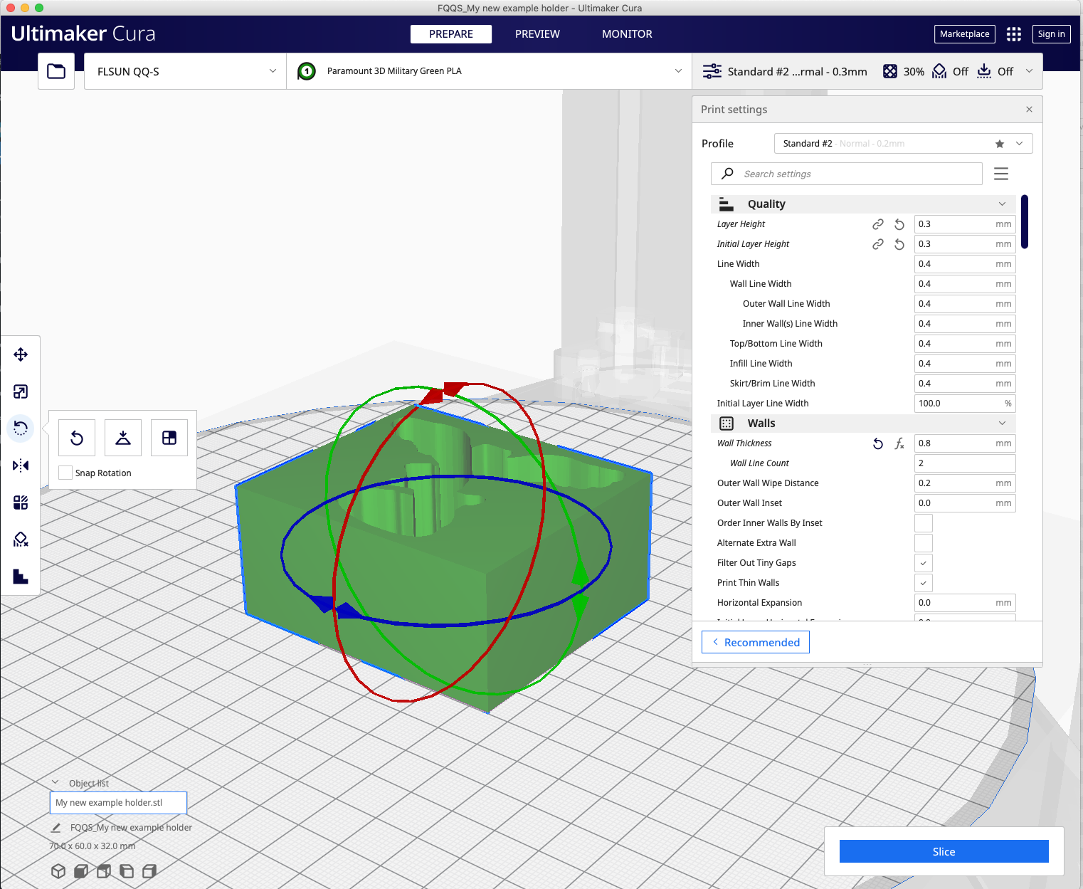
Step 10: Import the STL file into your slicer
You probably don’t need this part if you’re already familiar with 3D printing!
I use Ultimaker Cura to convert my STL files into the G-code format that 3D printers understand.
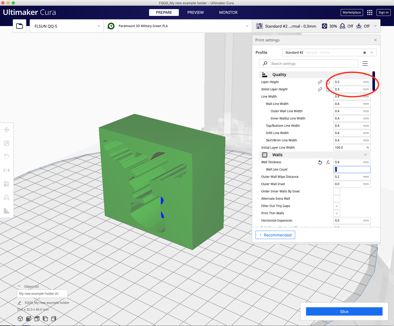
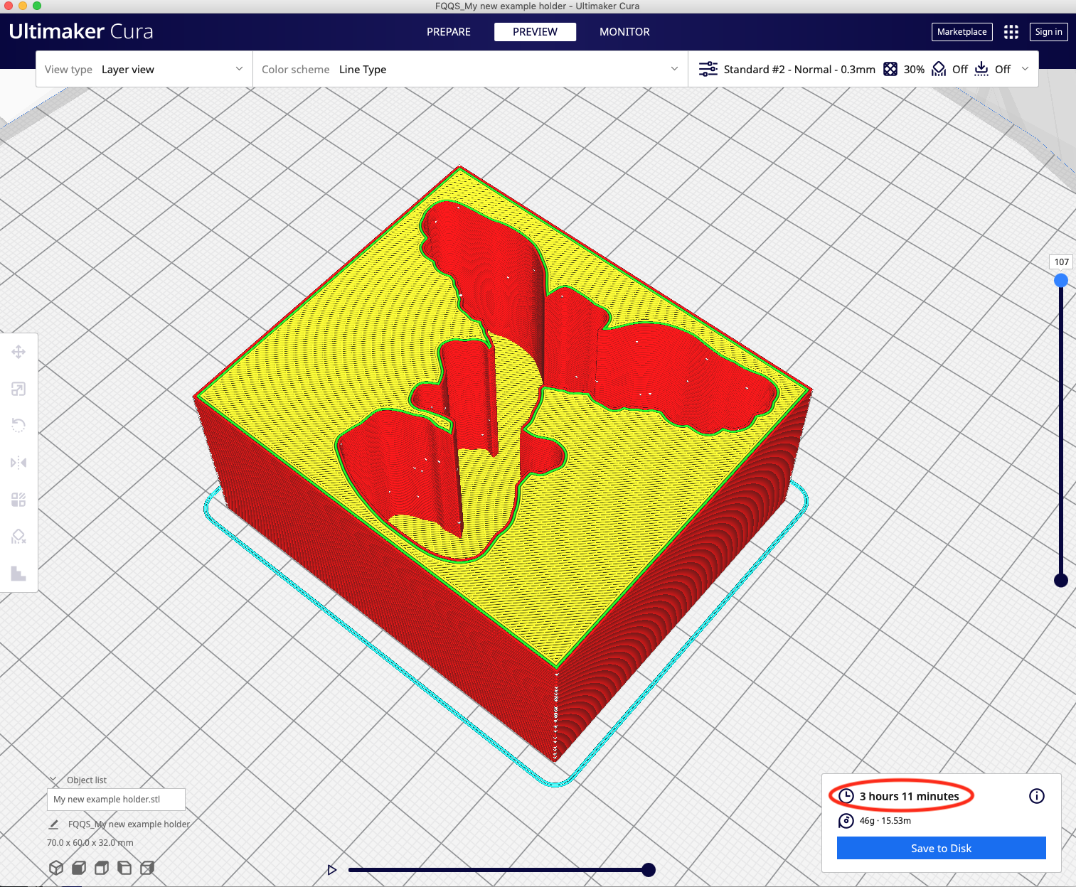
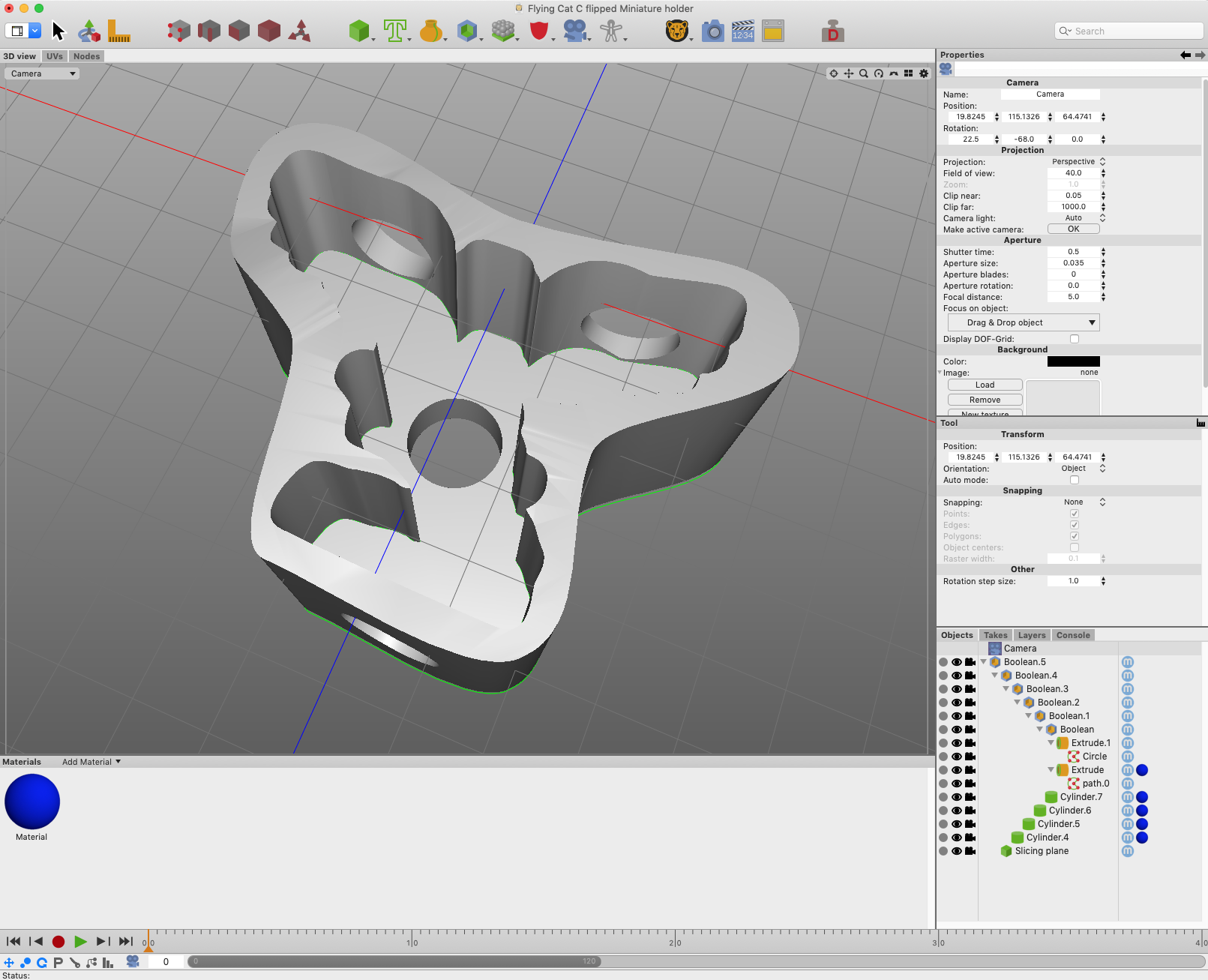
Step 8a: Prove you are the master of your 3D program
The reason why the above picture shows a relatively long printing time is that we’re printing a lot of material that we’ll never use. I made a “hole in a box” for instruction purposes, but as long as the hole is fully contained in a shape, there’s no reason for that shape to be a box.
When I first approached this design, I “carved out” portions of the box using additional boolean subtractions.
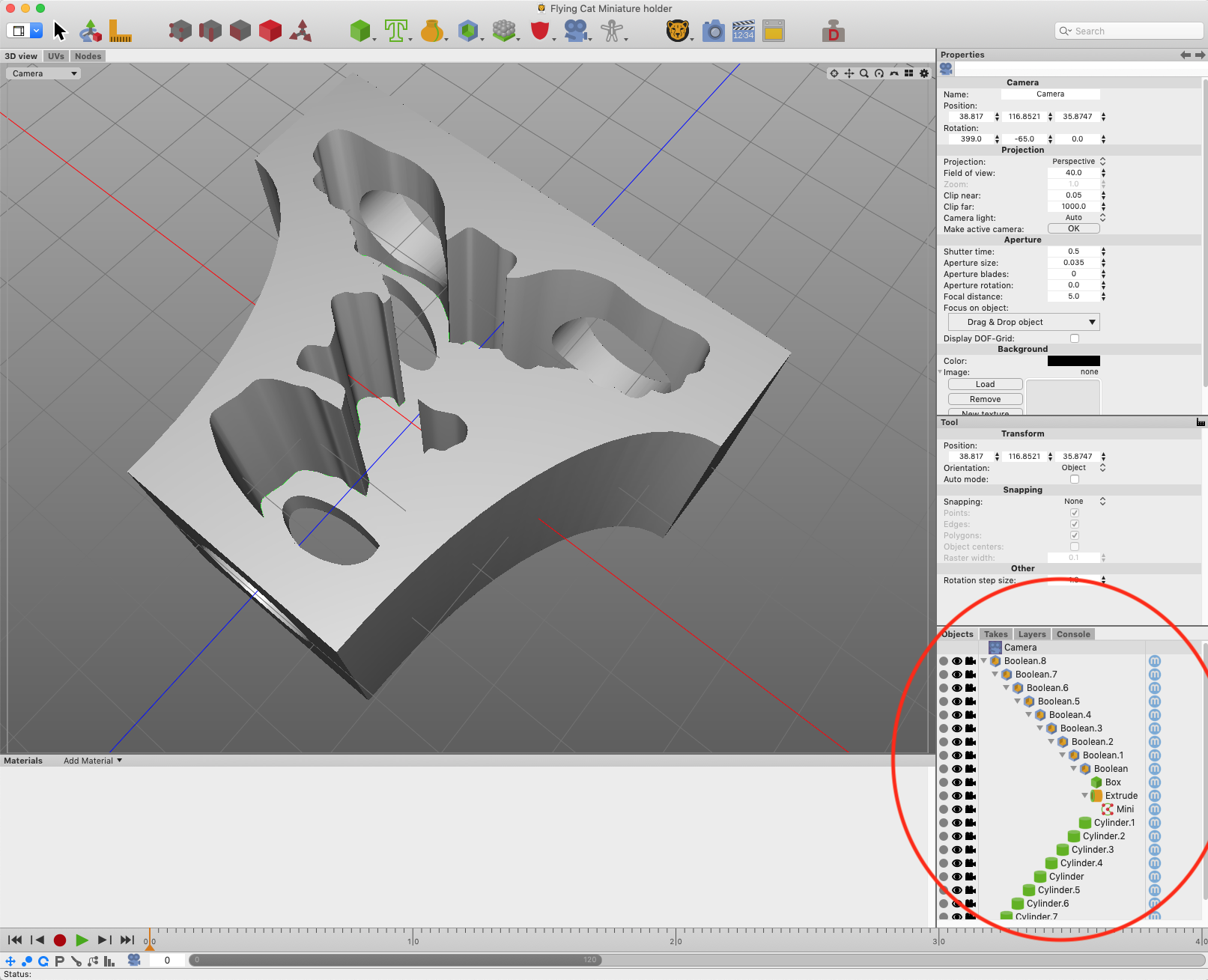
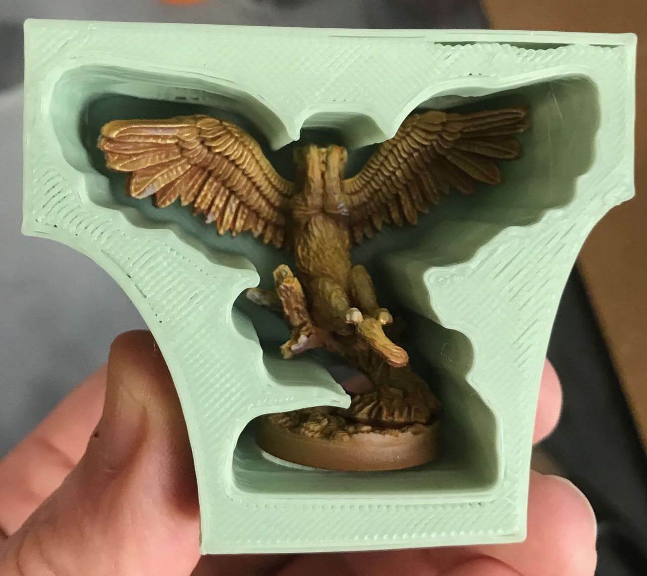
Why all the holes? For one thing, it means less plastic is printed. For another, in this style of 3D printing, a segmented wall is stronger than a simple smooth one; that’s because the slicer will put extra borders around the regions of the holes. The holes serve a couple of other functions: If the mini ever got stuck, I could reach through the holes to unstick it; if any liquid poured into the holder, it would have a chance to drain out before damaging the mini.
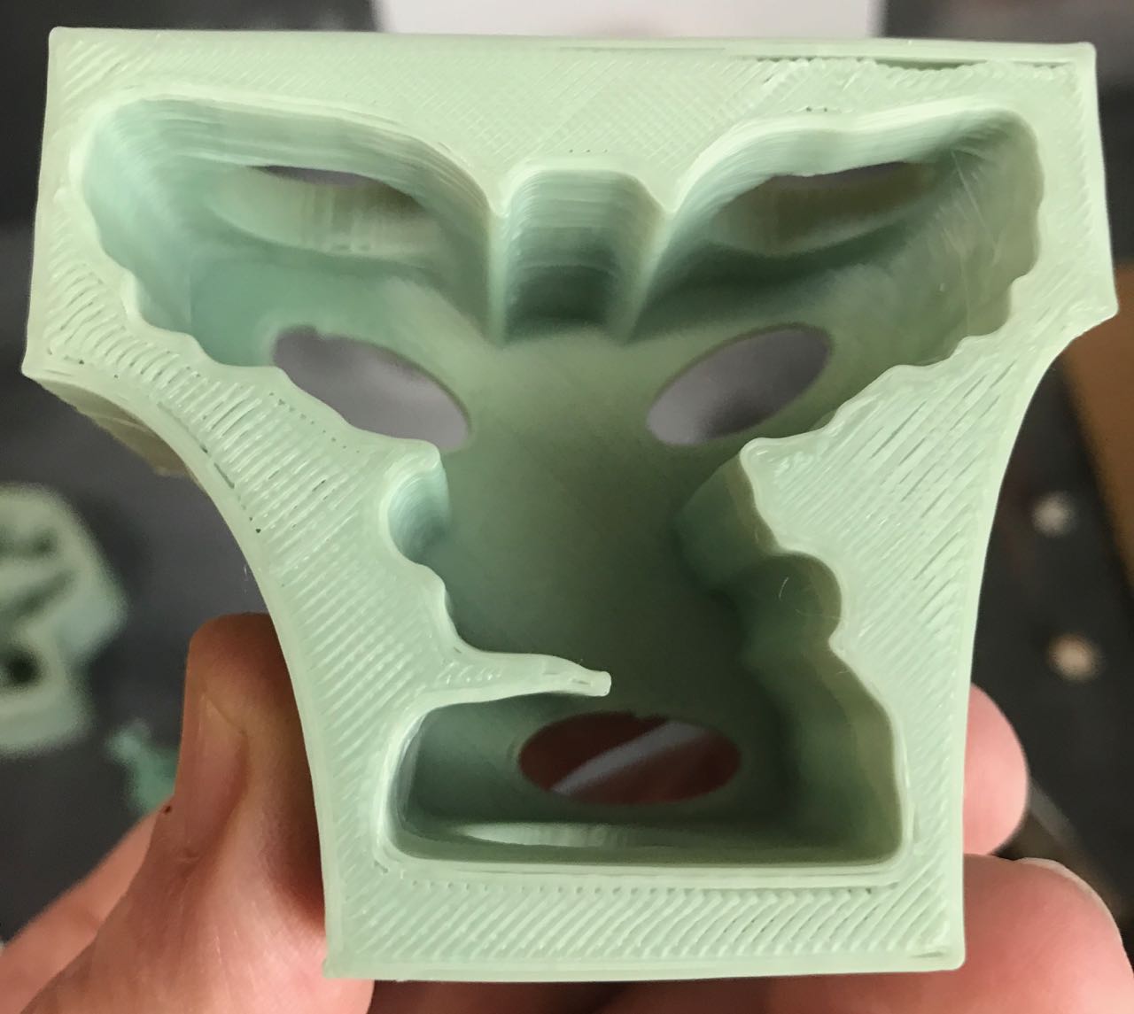
But do we really need a box? What if we could create a more efficient shape?
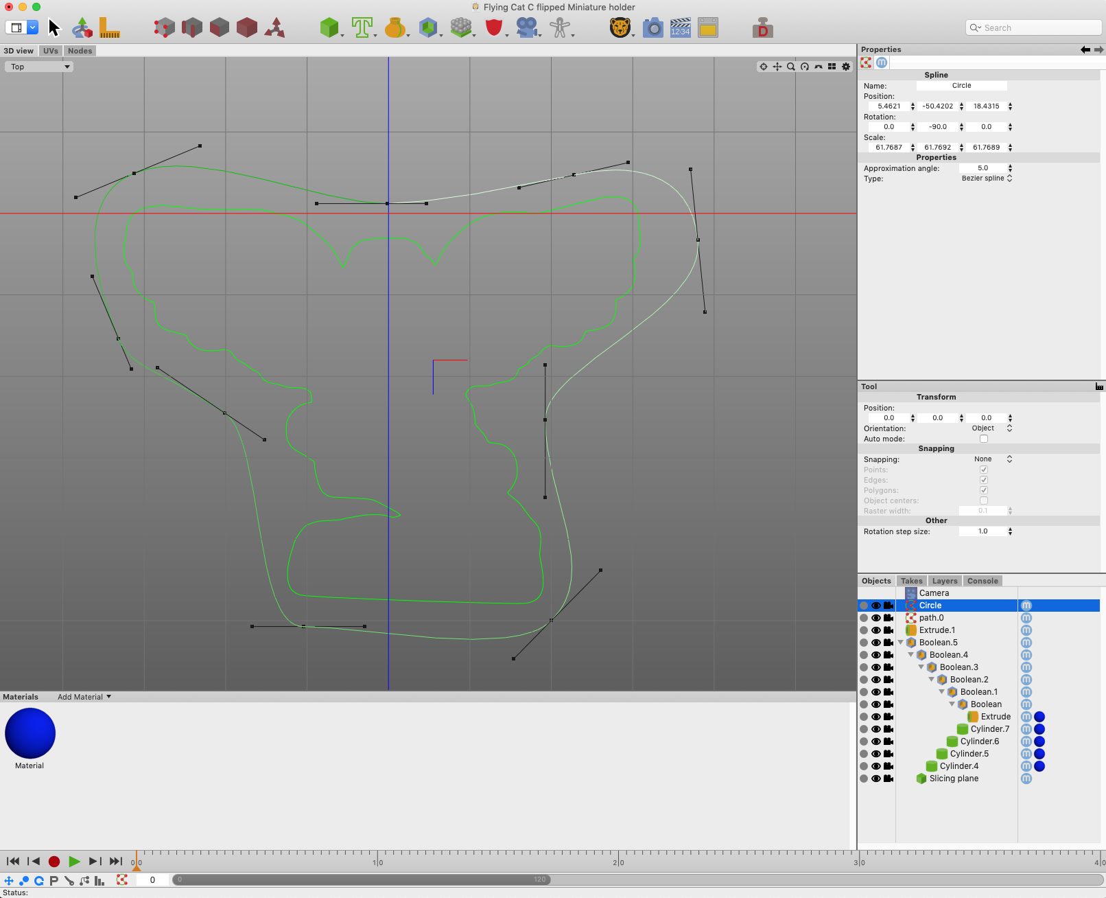
How does this look?
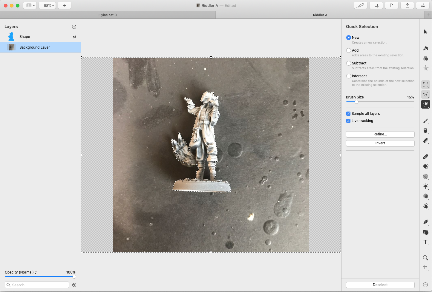
Remember that Riddler picture I had above? There was a reason why I worked with that image. The following example is left as an exercise for the student.
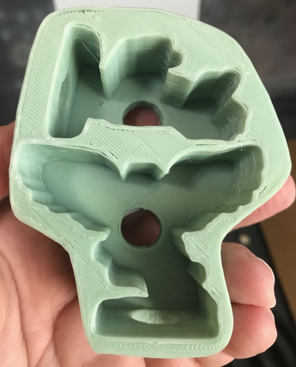
Finally, here’s your extra-credit homework assignment:
Pingback: A letter about 3D printing – The Argothald Journal