Did you read part 7 yet? If you thought to yourself “I don’t need to read part 7” that means you need to read part 7. (The exception is if you’re a licensed electrician, of course.)
Now I’ve reached the stage that Goldy is dreading: Working with power cords.
The point of this project was to use the solid-state relays attached to a Raspberry Pi to control the two “hot” power lines of my air conditioner using Apple’s HomeKit. I knew that this would require cutting open a power cord.
I knew I wasn’t going to cut apart my air conditioner’s power cord. If anything went wrong, I’d wind up with a dead A/C. Instead I purchased a NEMA 6-15 extension cord in order to cut it up. Here’s a picture of the two ends of the cord:

As a test, while I worked on the other steps of this project I describe in previous posts, I plugged male end of the extension cord into my apartment’s NEMA 6-15 outlet. With a multimeter, I verified that both “hot” wires (the horizontal sockets) were at 120 volts AC with respect to ground. Then I plugged my air conditioner into the female end of the cord and ran it for several hours. There were no problems, anomalous warm spots, or any other indication that the cord and A/C weren’t functioning as they were designed to do.
I removed the extension cord and did one last check with my multimeter. The resistance from the male to female ends of the extension cord for the corresponding poles to sockets was 0.2Ω. Nice job, Yung Li! Then I cut open Yung Li’s lovely power cord in the middle:

Not shown is the cut on my thumb I got when the Xacto knife slipped.
Now I had to figure out which of the three wires (white, black, or green) was the ground wire. If I’d had to guess, I would have guessed black, since that was the standard color of a ground wire in the electronics work I’d done so far. I would have been wrong. (You did read part 7, right?)
Fortunately, I did some homework. After searching on the web for a bit, I found found a couple of sites (like this one) that included pictures of the innards of a 6-15 power cord. Here’s the relevant image from the page I just linked:

Evidently the standard is that the green wire is ground.
With a prayer to both Guan Yin (Goddess of Mercy and Compassion) and Yung Li (Taiwanese manufacturer of the power cord), I cut the black and white wires. My multimeter verified that there was still continuity from the ground pole to the ground socket of the cord.
When I stripped the ends of the wires I’d cut, I saw that the wires were stranded. That was fine and not entirely unexpected. Sam Groveman felt that wrapping stranded wire around the screw terminals of a solid-state relay might be tricky (and dangerous; did you read part 7?), so instead he recommended that I get spade terminals and crimp them to the end of the wires. Here’s what the terminals looked like:

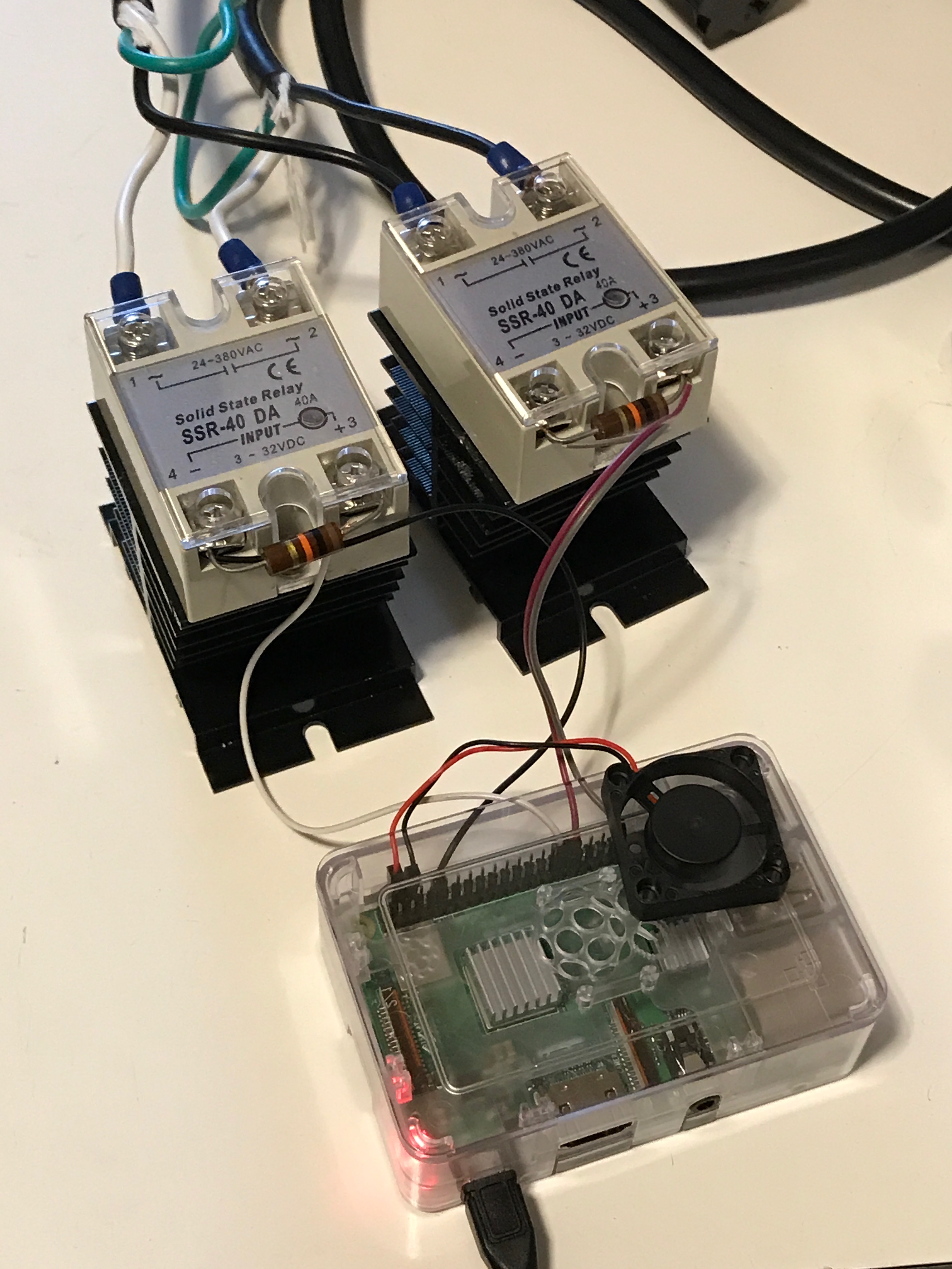
Here’s the initial set-up:

At this point, I hadn’t plugged the assembly into a power line yet. All I could do is verify my previous results: When HomeKit turned the relays off, the continuity between the two ends of the same line in the power cord was off; when the relays were on, the resistance between the two ends was about 6 kΩ. I knew that resistance from a multimeter had little meaning for alternating current (that’s why AC won over DC for household electricity), but it was reassuring nonetheless.
I’m sure you’re curious about how this worked when I applied AC power to this setup. However, before I tested that, I wanted to get the whole thing into a box; if there were going to be any problems, I didn’t want see them in a pile of relays and heatsinks and an RPi all dangling around.
I’ll get into the next step, and we’ll learn Goldy’s fate, in the next installment: the box.