Of course not!
The setup I described in my previous post has an issue that’s not obvious: the fans are on all the time. They’re powered by the +5V pins on the Raspberry Pi.
The fans were pretty quiet, but they were still audible in a quiet room. It was also a waste of power. I wanted the fans to only turn on when power was supplied to the solid-state relays.
At first, I had the brilliant idea of attaching the fans to GPIO pins, just as I had done with the relays. Fortunately, I did some homework; otherwise Goldy would have mocked me for days. It turns out that while the +5V pins can easily supply the 200mA required by the fans, the GPIO pins can only supply 16mA. If I had plugged the fans into the GPIO pins, it might have damaged the RPi’s circuit board.
Fortunately, I found this page which contained a simple circuit for controlling the fans from a GPIO pin. Here’s the circuit diagram from that page, redrawn by me:

I included some extra details in my diagram, because I hadn’t worked with transistors in years and needed the B, C, and E pins labeled on the diagram. It was also the first time I ever worked with diodes. I read up on working with transistors and diodes so I’d be able to tell how to put them in the circuit. I had some old 470Ω resistors, 2n222 transistors, and a breadboard from my old wizards’s staff project, but since I had to get new diodes and a breadboard jumper wires anyway, I decided to spend the extra few bucks for new breadboards and transistors.
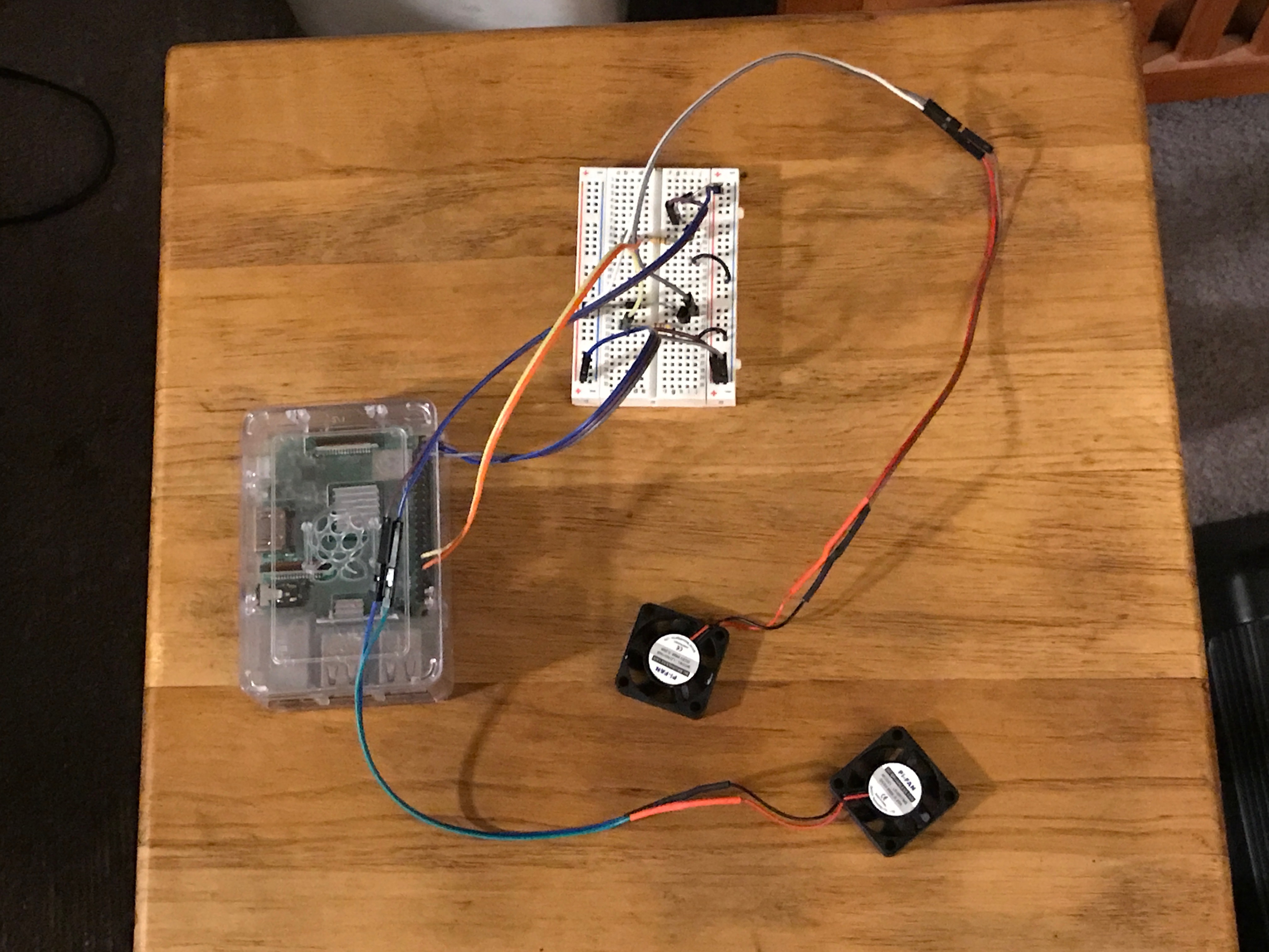
Here’s what it looked like when I installed two sets of components for the above circuit and tested it with my Raspberry Pi:

It’s a bit of a mess, but it worked: I could turn the fans on and off via gpio commands.
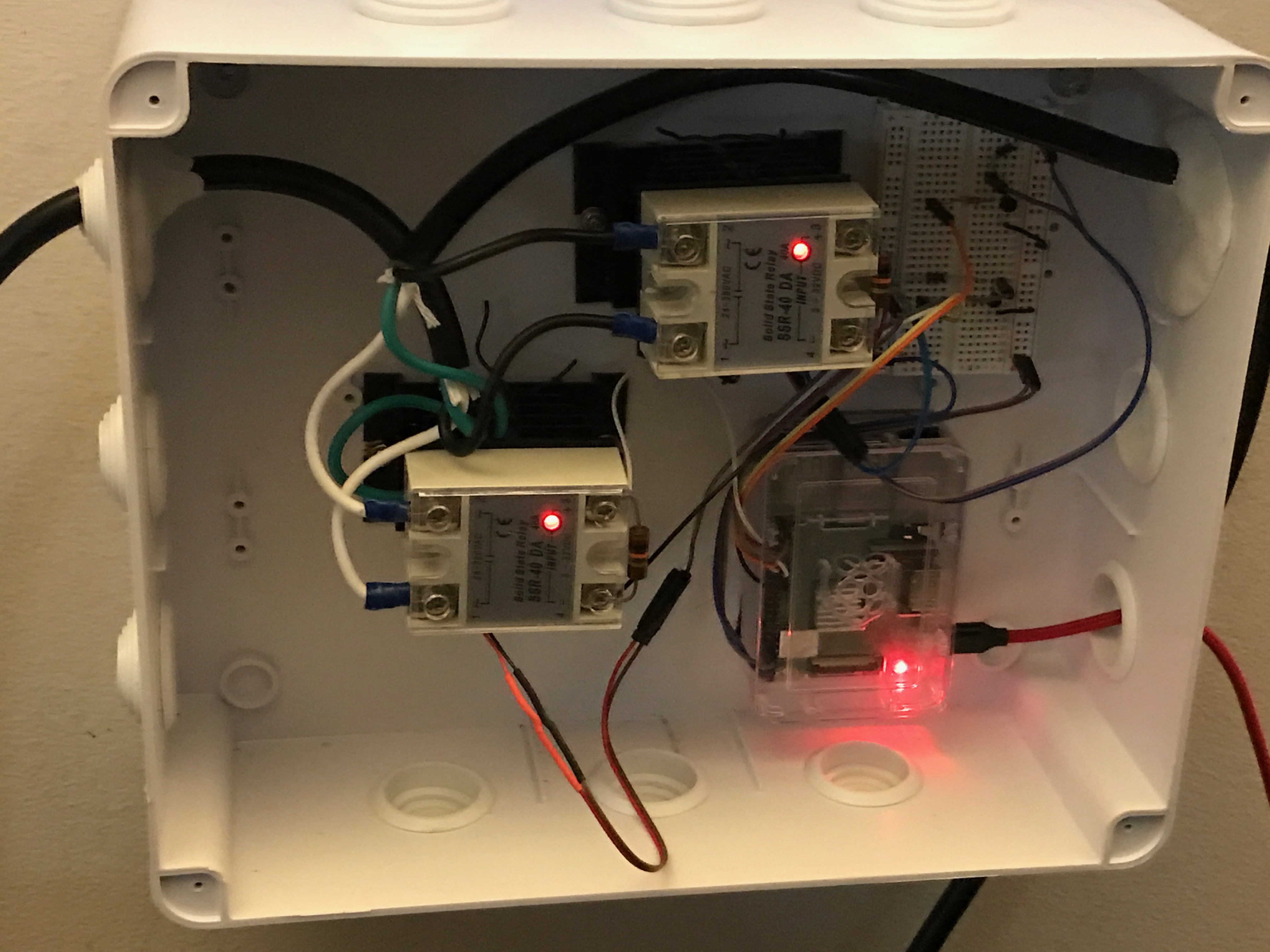
Next I put the assembly in the box, which made things look even messier:

Again, it all worked.
I’m aware that for a “finished” product, I should have transferred the transistors, diodes, and resistors to a printed circuit board. In fact, they make circuit boards of the same size, shape, and pin layout of the breadboard so you can transfer the components to the same sockets and solder them in place. However, I wasn’t prepared to try to resurrect my old soldering skills. The breadboard came with a sticky backing that I used to fix it in the box. So far, none of the components have shown any inclination to shake themselves loose.
Next came getting the box mounted on my wall near the air conditioner. I quickly learned two things:
- The project enclosure box was not designed to be mounted on a wall.
- The cable of the micro-USB power supply that came with the Canakit was not long enough to reach from where I wanted to mount the box to the nearest available electrical outlet.
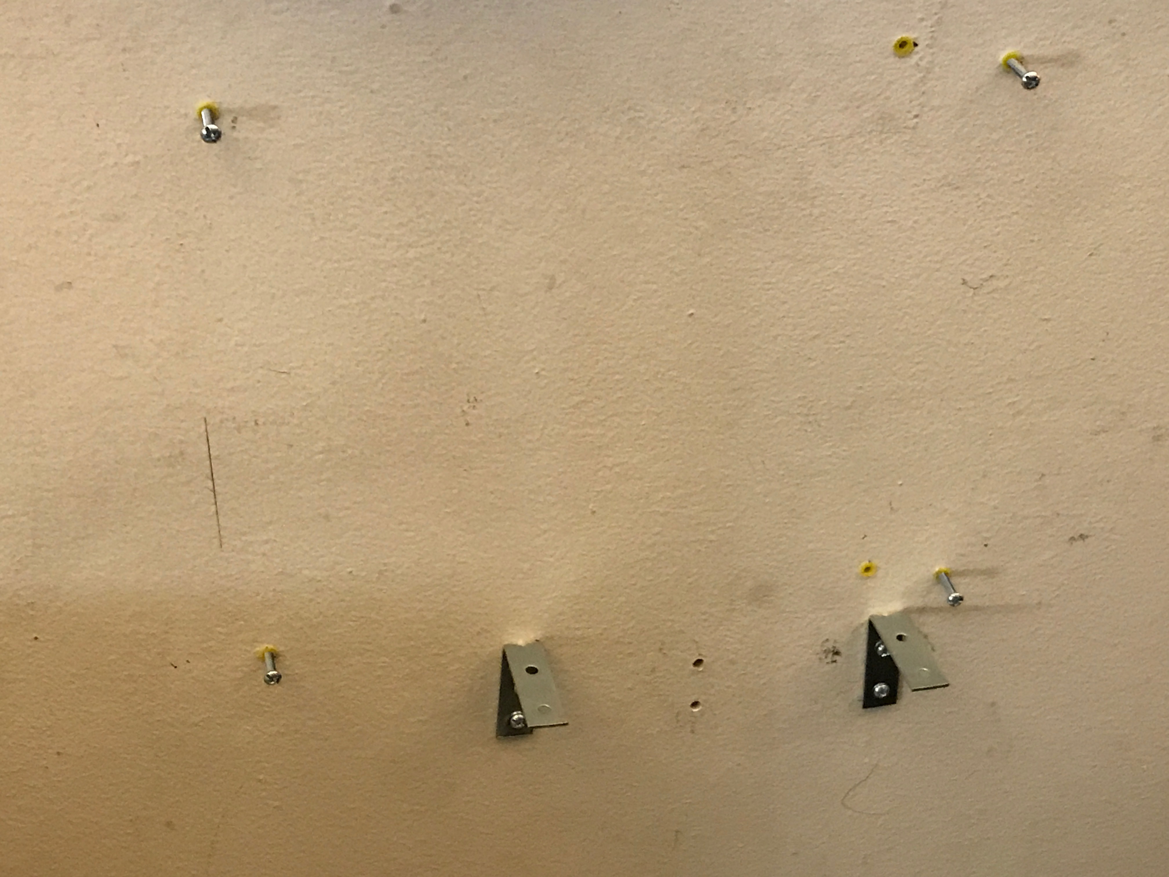
To deal with the first issue, I drilled some holes in the wall and use dry-wall anchors and bolts that fit in indentations in the back of the box. That wasn’t enough to hold it up, so I added some angle brackets:

That still wasn’t enough, so finally I conceded “defeat”, drilled a couple of additional holes in the back of the box, and used dry wall screws to fix it in place:

You can see my expert carpentry skills: Even though I used to a level to set up everything, the box still came out slightly crooked. Fortunately, it’s located behind my TV set where it’s not visible to the casual observer.
To handle the second issue, I purchased a USB charger and a separate 10-foot-long micro-USB charger cable. Before I placed the box on the wall, I tested this combination for several days to make sure the Raspberry Pi wouldn’t overheat or display any unusual symptoms.
As I type these words, my air conditioner has been running for several hours with power supplied through this box. The heat sinks are only slightly warm at best. Goldy is still nervous, but she’s becoming more relaxed with each passing hour.
Alternatives
In the first post in this series, I asked if there was any existing way to control a 230V air conditioner via HomeKit. It wasn’t until half-way through the project that I found this Reddit post. It turns out that people who own pool water heaters have to deal with this problem too, and they have several solutions.
Of the ones discussed in that post, if I had known about it I would have purchased the ELK-9200 Heavy Duty Relay. Its containing box is 12″x12″x3″, somewhat larger than the enclosure I went with, but it’s designed by professionals and is doubtless safer. I still would have had to cut apart power cords, so Goldy would still have cause to be anxious (and you would still have to read part 7).
On the other hand, if you’ve added up the cost of all the materials I purchased for this project, the ELK-9200 would have cost about half as much.
Wrapping it up
Here we are, at the end of my longest series of blog posts since I wrote about a road trip I took in 2008. That saga had radiant fruits of passion; this saga had an imaginary talking goldfish. It all balances out.
I now have the parts for future Maker projects if I’m so inclined. I have a Raspberry Pi, which is a pretty decent little computer. I may install another HomeBridge module that would give me some control over my PS4.
I learned quite a bit, I made a new imaginary friend, and got some more practice writing blog posts. All in all, it was a positive experience.