In the last part of this overly-extended saga, I described how I got a Raspberry Pi to send signals to the pins on its circuit board. The next step is to get the signal from those pins to control the flow of electricity through a 240V power cord.
I found several posts on the web (here’s one) that suggested a good way to do this was with solid-state relays. Here’s the picture from that last link:
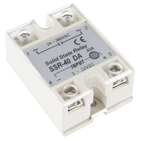
The idea is that a low voltage can be turned on or off on the lower terminals of the relay, and that will allow or block a high voltage across the upper pins. From the label (and the technical specs) of that relay, I knew that from 3V-32V volts DC on the two lower terminals could control up to 380 volts AC on the upper terminals; the GPIO pins would be at 3.3V when turned on and a NEMA 6-15 power cord would carry around 120V AC per wire. The label on both the air conditioner and the rating of the power cord told me that the relay would have to handle up 15 amps, so I got a relay that could handle 40A.
In other words, I made sure to get a relay with specs much higher than I would need to handle the volts and amps it would be switching.
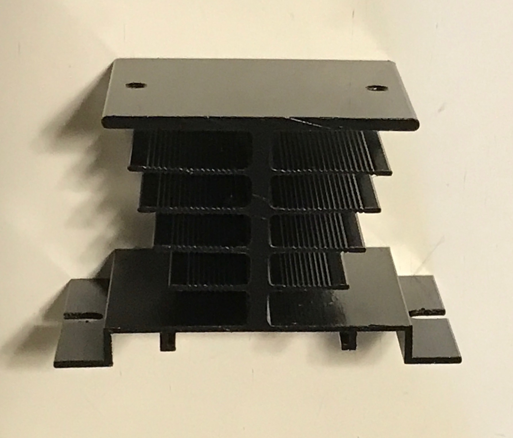
Did I trust that? No, of course not! When you pass that much voltage and amps through a small device, the chief risk is that it might get hot. This is a recognized issue with solid-state relays, and they make special heat sinks for them. I purchased this set of three, which came with the necessary screws to attach the relays. I also picked up some thermal paste to improve the heat transfer between the relay and the heat sink.
Here’s one of the heat sinks:
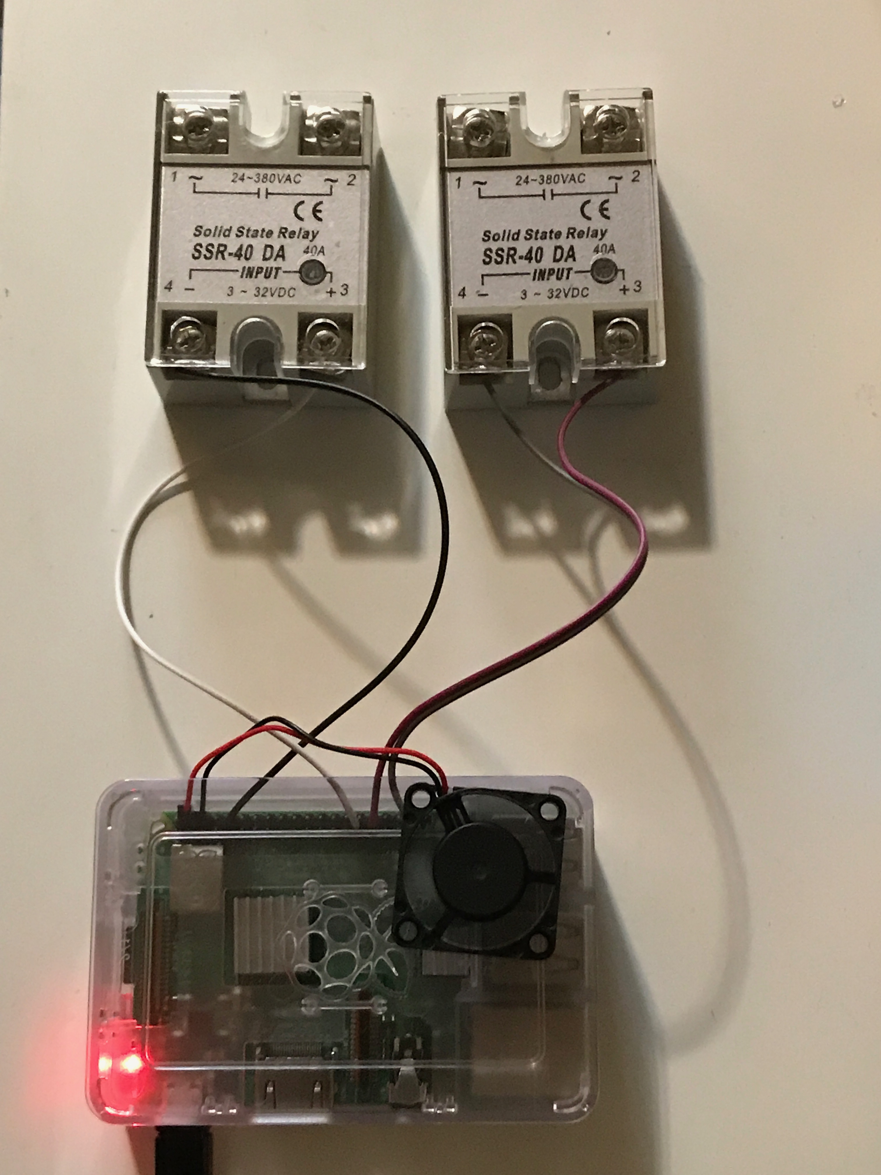
Was that enough? I still wasn’t sure. So I got a couple of fans that could be powered by the 5V pins on the Raspberry Pi. That’s why you can see a fan in most of the Raspberry Pi pictures; I wanted to make sure it would keep spinning no matter what I did.
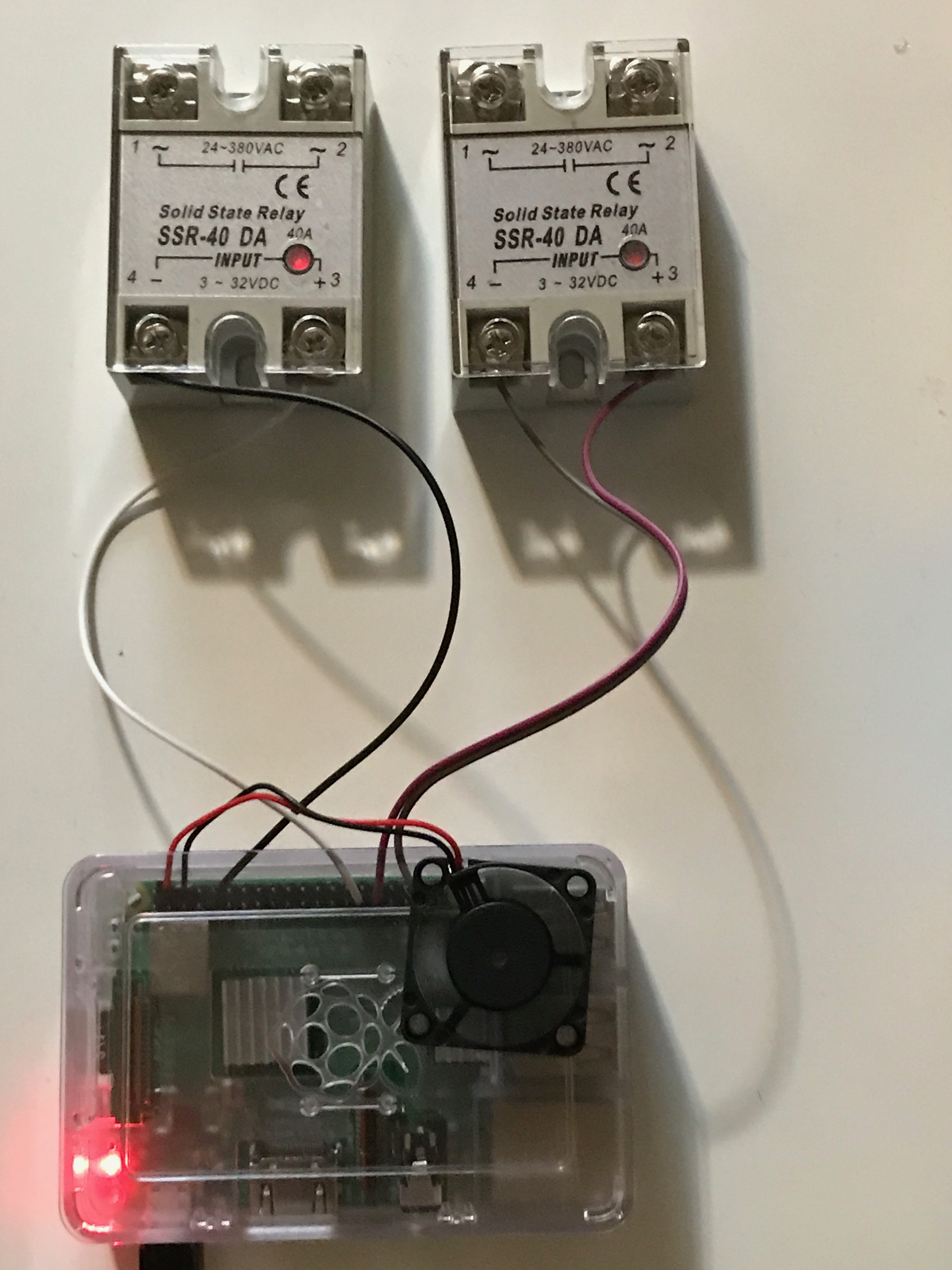
I connected the relays to the GPIO pins (while the Raspberry Pi was off, of course):
Then I turned on the voltage on the Raspberry Pi using Homekit:
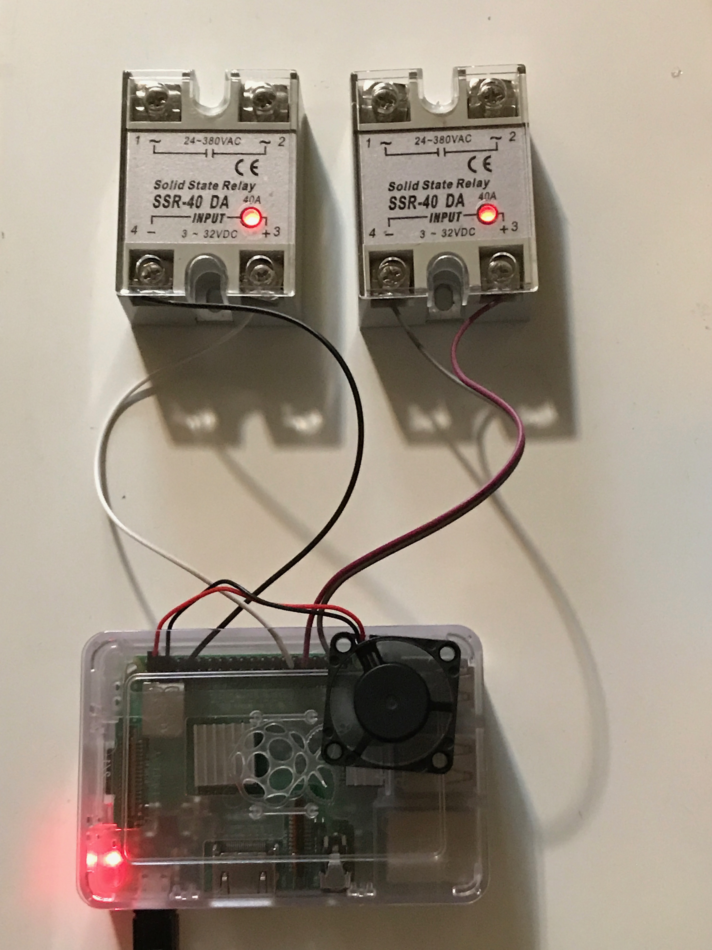
Aha! The LEDs on the relays turned on! At least up until this point, I was doing something right.
I used a multimeter to see if I could spot anything across the the upper terminals of the relays. I found that with the relays off, a continuity test failed; with the relays on, the resistance across the upper terminals went to about 6 KΩ. This demonstrated that some electrical characteristic was changing in the upper terminals in response to the signal on the lower terminals, though it didn’t prove the relays could switch 120V.
Everything was fine until I turned the Raspberry Pi and then on again. For about 15 seconds after I turned it on, the LEDs on the relays were “half-lit”:
My multimeter read 1.6V across the GPIO pins during this time. The top terminals of the relays remained off, but I still wasn’t happy. I didn’t want there to be any chance that my air conditioner would turn on just because my apartment had a power outage.
It was Sam Groveman who gave me the answer. I used my chosen GPIO pins on the Raspberry Pi as output pins. On an RPi, an output pin doesn’t need a pull-down resistor; the output pins are automatically pulled. However, when the RPi boots up, by default all the GPIO pins are set to input, with no defined output voltage. An input pin does need a pull-down resistor; otherwise the voltage “floats”. When my multimeter read 1.6V, it was probably because the actual voltage was fluctuating rapidly between 0 and 3.3V.
I tried to solve the problem by explicitly turning off the pins as part of the boot process. I put the “turn-off” command in /etc/rc.local. But the contents of that file are executed at the very end of the boot procedure, so the relays did not go into a genuine “off” state until 15 seconds after the RPi powered on.
I looked up how to change the default pin behavior. That procedure turned out to be tricky because I used NOOBS to install the operating system. In retrospect, I should have done a direct Raspian image installation.
I could have reinstalled Raspian from scratch, but there was a simpler way: put in pull-down resistors. Fortunately, I had some left-over 10 KΩ resistors from a different project I worked on in 1990.
The final circuit diagram, pull-downs and all, was:

After I added those resistors, the LEDs on the relays remained dark through the entire Raspberry Pi boot process. Here’s the set-up with the resistors in place:
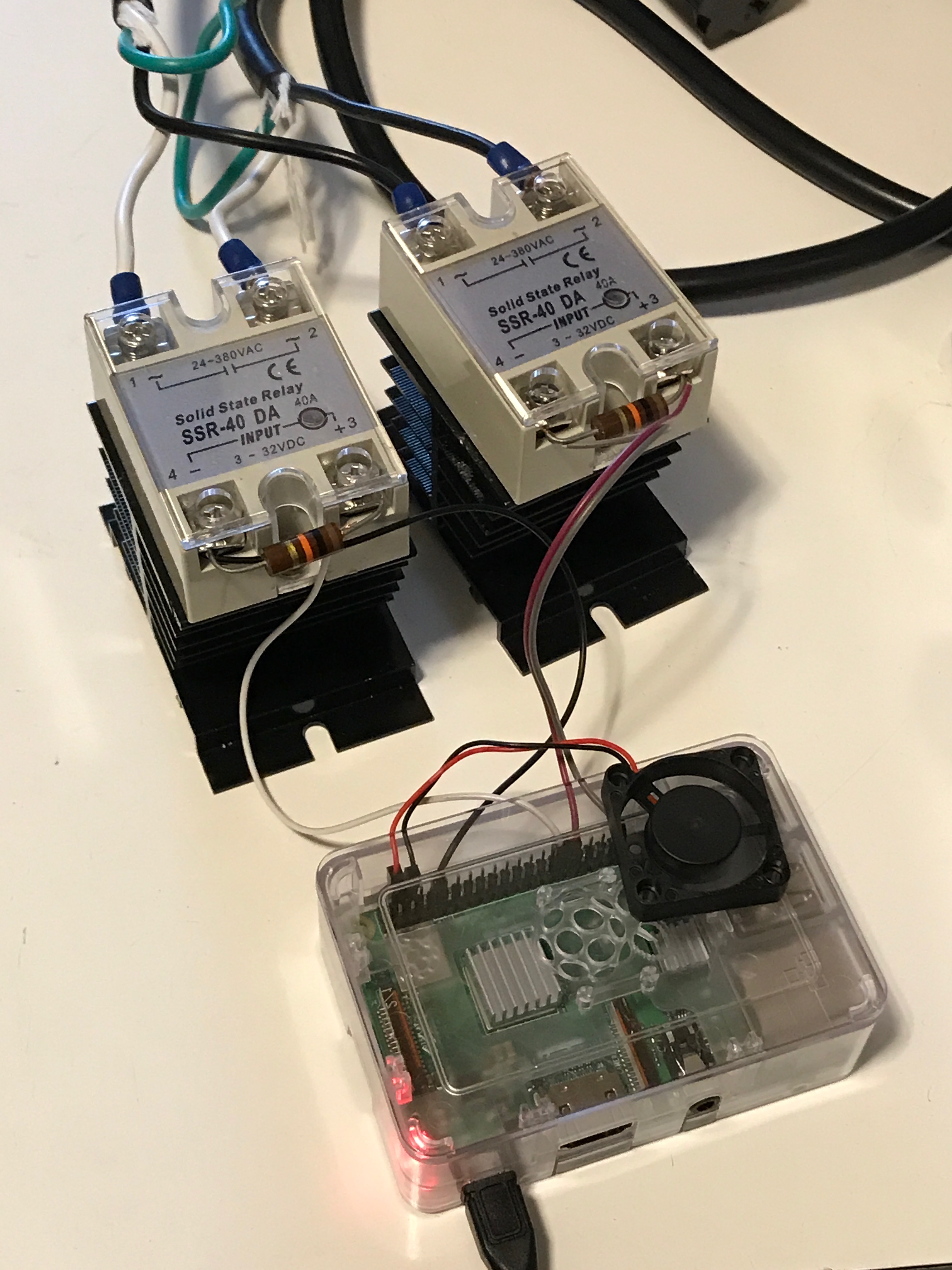
If you’re keen of eye, you’ll notice some power cords in that picture and in the circuit diagram. I’ll get to that in a subsequent blog post. Before that, I have to deal with the next step of this project: electrocuting goldfish.
Pingback: 230V Air Conditioner and HomeKit, part 7: Electrocuting Goldfish – The Argothald Journal
Pingback: 230V Air Conditioner and HomeKit, part 8: Power Cords – The Argothald Journal
Pingback: 230V Air Conditioner and HomeKit, part 9: The Box – The Argothald Journal